Metal pipe cutting device

A cutting device, metal pipe technology, applied in the direction of pipe cutting device, shearing device, positioning device, etc., can solve problems such as damage to equipment, cutting to equipment, etc.

Active Publication Date: 2018-06-01
宁波隆锐机械制造有限公司
View PDF9 Cites 3 Cited by
  • Summary
  • Abstract
  • Description
  • Claims
  • Application Information

AI Technical Summary

Problems solved by technology

[0005] The present invention intends to provide a cutting device for metal pipes to solve t...

Method used


Image

  • Metal pipe cutting device
  • Metal pipe cutting device

Examples


Embodiment Construction

[0017] The present invention will be described in further detail below by means of specific embodiments:

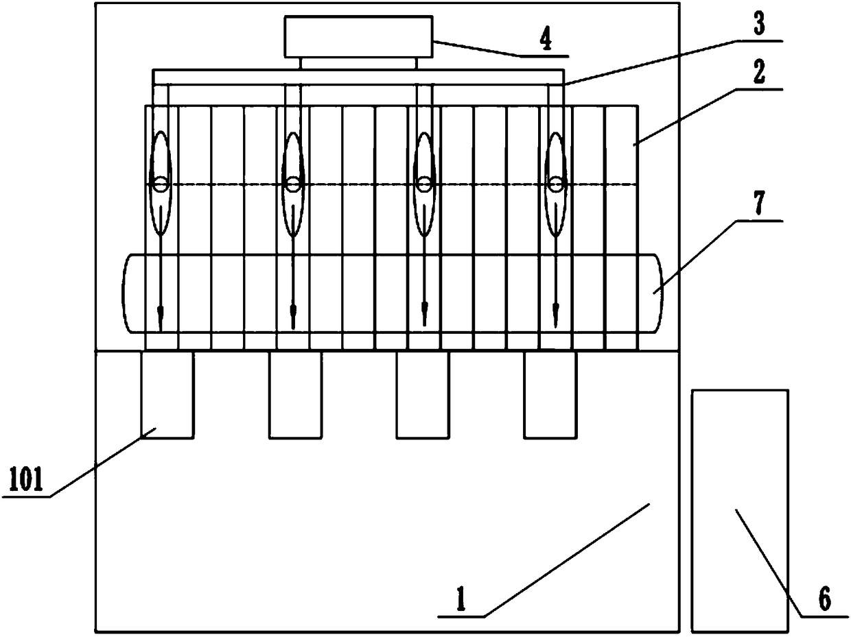
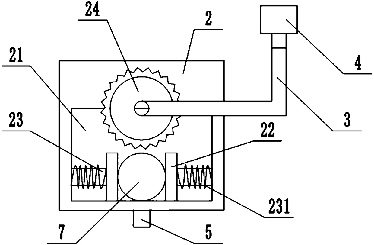
[0018] The reference signs in the accompanying drawings include: cutting base 1, groove 101, plate 2, opening 21, clamp block 22, connecting rod 23, elastic member 231, circular cutter 24, shaft 3, cylinder 4, lift Column 5, receiving box 6, metal pipe 7.

[0019] The embodiment is basically as attached figure 1 , attached figure 2 Shown: a cutting device for a metal pipe 7, including a cutting base 1, the upper surface of the cutting base 1 is provided with a number of evenly distributed grooves 101, the top of the cutting base 1 is provided with closely fitting and neatly arranged Several sheet plates 2, the cutting base 1 is an "L"-shaped base, and the sheet plates 2 are all slidably connected to the inner vertical part of the "L"-shaped cutting base 1, and the sheet plates 2 are provided with Opening 21, the thickness of the sheet 2 is less than the thickness of t...


PUM


Abstract

The invention relates to a cutting machine, in particular to a metal pipe cutting device which comprises a cutting base. The cutting base is provided with a plurality of grooves in uniform distribution and further provided with a plurality of sheets which are closely attached and orderly arrayed, and the sheets are in slide connection with the cutting base and provided with openings. One end of each opening is symmetrically provided with two clamping blocks, one end of each clamping block is connected with a connecting rod, the other end of each connecting rod is connected with the corresponding sheet, an elastic part sleeves each connecting rod, and cutters are arranged at intervals at the other ends of the openings. Inner upper ends of the sheets are partially provided with the cutters,lower ends of the sheets are provided with the clamping blocks for clamping metal pipes, the sheets with the cutters move downwards to allow the cutters in the sheets to cut the metal pipes into corresponding sections in a moving process, the sheets with the cutters can be stored in the grooves, and equipment damages in cutting are avoided. The problem of equipment damages in a cutting process inthe prior art is solved.

Description

technical field [0001] The invention relates to a cutting machine, in particular to a cutting device. Background technique [0002] At present, in general pipe processing, in order to meet the needs of pipe fitting design, in addition to repairing the weld part of the pipe fitting, it also includes a cutting step according to the length of the pipe fitting design. This step can be combined with the welding seam part The repair is carried out continuously. When actually cutting the metal pipe, the method usually used is to pull out the metal pipe to be cut section by section, and the cutting knife is fixed and falls in the interval time. Since the cutting knife is not synchronized, it is easy to cause the incision to be inconsistent. Smooth, and most of the current cutting machines are aimed at cutting a long section at a time. Metal pipes usually need to be cut into a small section. If the original cutting machine is used to cut only one section at a time, it will waste manp...

Claims


Application Information

Patent Timeline
IPC IPC(8): B23D21/00B23Q3/06
CPCB23D21/00B23Q3/064
Inventor 项文增
Owner 宁波隆锐机械制造有限公司
Why Eureka
Try Eureka