Pneumatic stop valve

A pneumatic shut-off valve and cylinder-driven technology, which is applied in the direction of valve lift, valve details, valve device, etc., can solve the problems of difficult valve head replacement and repair, and achieve the effect of expanding the scope of use and improving practical value

Pending Publication Date: 2018-06-01
上海悟道机电设备有限公司
View PDF10 Cites 2 Cited by
  • Summary
  • Abstract
  • Description
  • Claims
  • Application Information

AI Technical Summary

Problems solved by technology

[0003] The purpose of this application is to provide a pneumatic globe valve to solve the problem that the conventional pneumatic globe valve has a single-stroke cylinder, valve core and valve body as an integral structure, and the valve head is difficult to replace and repair after partial pressure loss

Method used


Image

  • Pneumatic stop valve
  • Pneumatic stop valve
  • Pneumatic stop valve

Examples


Embodiment Construction

[0022] The application will be described in further detail below in conjunction with the accompanying drawings.

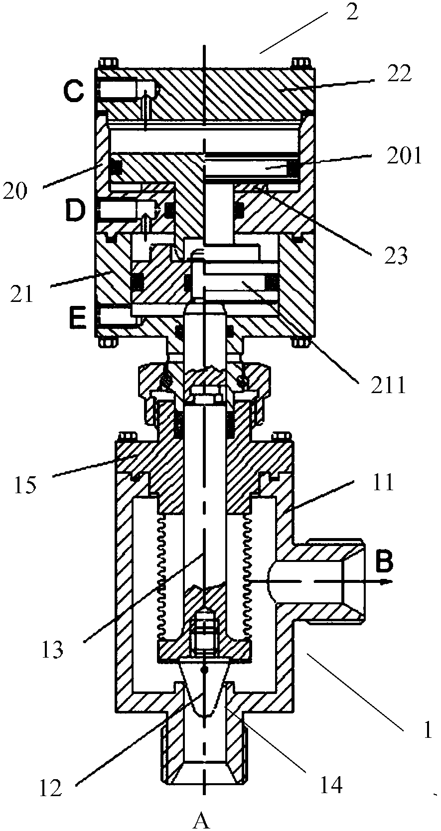
[0023] figure 1 A schematic diagram of the structure of the pneumatic shut-off valve in an embodiment of the present application is shown. The pneumatic shut-off valve includes: a valve body device 1 and a cylinder drive device 2, wherein the cylinder drive device 2 includes a cylinder upper chamber 20 and a cylinder lower chamber 21 , an upper piston 201 and a lower piston 211; the valve body device 1 includes a valve body 11, a valve head 12, a valve core 13 and a valve seat sealing surface 14; an upper piston 201 is arranged in the upper cavity 20 of the cylinder, and the cylinder The lower chamber 21 is provided with a lower piston 211, and the combined force of the upper piston 201 and the lower piston 211 is used to drive the valve body device 1 into the corresponding working mode of the valve; the inner cavity of the valve body 11 is provided with Vertical ...


PUM


Abstract

The invention provides a pneumatic stop valve. The pneumatic stop valve comprises a valve body device and a cylinder driving device, wherein the cylinder driving device comprises a cylinder upper cavity, a cylinder lower cavity, an upper piston and a lower piston; the valve body device comprises a valve body, a valve head, a valve element and a valve base sealing surface; the upper piston is arranged in the cylinder upper cavity; the lower piston is arranged in the cylinder lower cavity; the valve body device is driven to enter a working mode corresponding to the valve through synthesized acting force of the upper piston and the lower piston; the vertical valve element is arranged in an inner cavity of the valve body; the upper end of the valve element is connected with the cylinder driving device; the lower end of the valve element is connected with the valve head; and through a driving effect of the cylinder driving device on the valve body device, the valve head and the valve base sealing surface form the working mode of the valve. The pneumatic stop valve adopts a split valve head design, so that the valve head is simply maintained and replaced, and the use and maintenance costs of the valve are greatly reduced.

Description

technical field [0001] The present application relates to the technical field of valves, in particular to a pneumatic shut-off valve. Background technique [0002] In the air tightness test or fluid control, if the control of high-pressure gas is directly controlled by manual control such as valves, there will be disadvantages such as untimely control, loose control, and inability to realize remote control. If the gas shut-off valve controls the high-pressure fluid with low-pressure gas, remote control and timely control can be realized. However, the main conventional functions of the existing gas shut-off valve are two states of "on and off". According to the flow range of the required control medium, the user determines to select the valve product of the corresponding specification. Conventional pneumatic globe valves mostly use a single-stroke cylinder to connect with the valve core, and the structure of the overall design of the valve core and the valve head, when the va...

Claims


Application Information

Patent Timeline
Patent Type & Authority Applications(China)
IPC IPC(8): F16K1/00F16K31/122
CPCF16K1/00F16K31/122
Inventor 郝鹏程苏根长戴文元吴嵚崟蒋小燕张芸茜耿文忠
Owner 上海悟道机电设备有限公司
Why Eureka
Try Eureka