Shell-and-tube heat exchanger performance testing device and testing way

A technology of shell-and-tube heat exchanger and testing device, which is applied in the direction of material thermal development, etc., and can solve the problems of single non-adjustable test method and unstable measurement data.

Pending Publication Date: 2018-06-01
NANHUA UNIV
View PDF0 Cites 9 Cited by
  • Summary
  • Abstract
  • Description
  • Claims
  • Application Information

AI Technical Summary

Problems solved by technology

[0003] The purpose of the present invention is to overcome the deficiencies of the prior art, and provide a performance testing device and testing method for a shell-and-tube hea...

Method used


Image

  • Shell-and-tube heat exchanger performance testing device and testing way
  • Shell-and-tube heat exchanger performance testing device and testing way
  • Shell-and-tube heat exchanger performance testing device and testing way

Examples


Embodiment 1

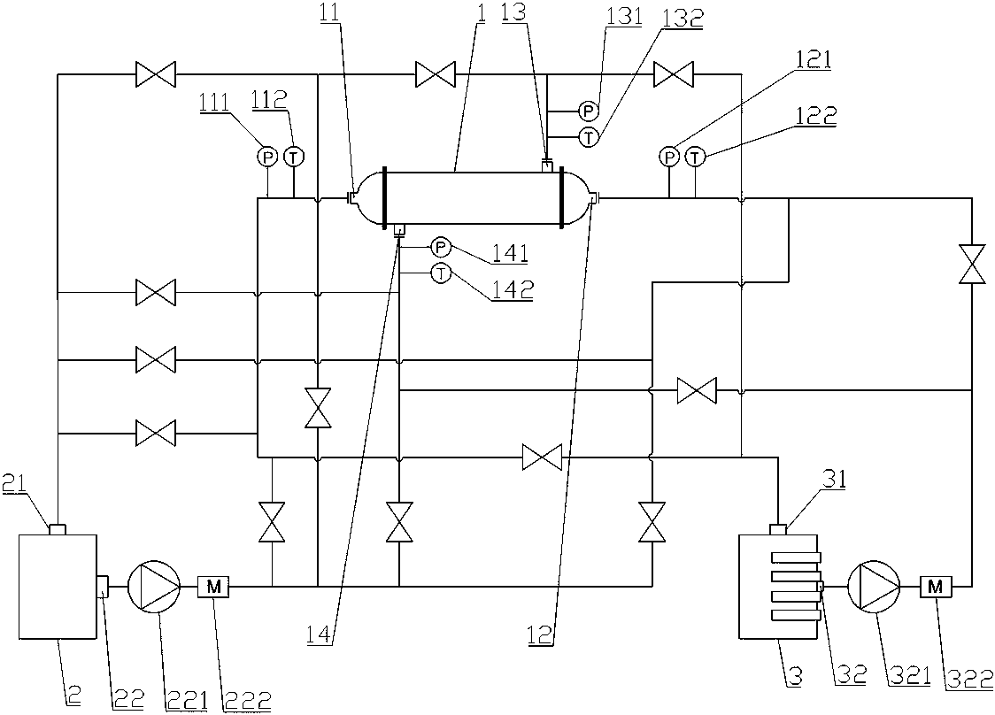
[0073] Such as figure 1 , 2 As shown, the shell-and-tube heat exchanger performance testing device includes a shell-and-tube heat exchanger 1, a cold water tank 2, a hot water tank 3 and a computer.

[0074] The shell-and-tube heat exchanger 1 is provided with a tube-side cavity and a shell-side cavity that are not connected to each other. The shell of the shell-and-tube heat exchanger 1 is provided with a tube-side No. 1 port 11 and The No. 2 port 12 of the tube side is also provided with the No. 1 shell side port 13 and the No. 2 shell side port 14 connected to the shell side cavity. The No. 1 tube side port 11 is provided with a pressure sensor A111 and a temperature sensor A112. No. 2 port 12 is provided with pressure sensor B121 and temperature sensor B122. No. 1 port 13 of shell side is provided with pressure sensor C131 and temperature sensor C132. No. 2 port 14 of shell side is provided with pressure sensor D141 and temperature sensor D142. The first port 11 of the t...

Embodiment 2

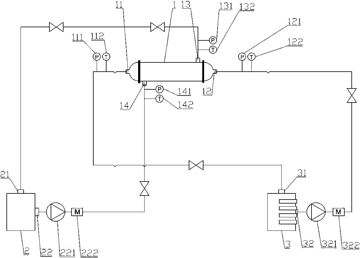
[0127] Such as figure 1 , 3 As shown, the only difference between this embodiment and embodiment 1 is that a specific pipeline different from that of embodiment 1 is selected in the pipeline network to form a test method different from that of embodiment 1.

[0128] In the test method of this embodiment, the hot fluid and the cold fluid flow in the same direction in the shell-and-tube heat exchanger, the hot fluid flows through the tube-side cavity of the shell-and-tube heat exchanger, and the cold fluid flows through the tube-side cavity of the shell-and-tube heat exchanger. Shell cavity.

[0129] Pipeline selection in this embodiment: open the valves on pipeline B, pipeline F, pipeline J and pipeline N, and close the valves on the remaining pipelines in the pipe network; at this time, the water inlet 21 of the cold water tank 2 passes through The pipeline B communicates with the shell-side No. 2 port 14 of the shell-and-tube heat exchanger 1, the water outlet 22 of the col...

Embodiment 3

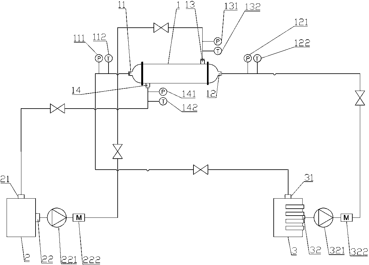
[0131] Such as figure 1 , 4 As shown, the only difference between this embodiment and embodiment 1 is that a specific pipeline different from that of embodiment 1 is selected in the pipeline network to form a test method different from that of embodiment 1.

[0132] In the test method of this embodiment, the hot fluid and the cold fluid flow in opposite directions in the shell-and-tube heat exchanger, the cold fluid flows through the tube-side cavity of the shell-and-tube heat exchanger, and the hot fluid flows through the tube-side cavity of the shell-and-tube heat exchanger. Shell cavity.

[0133] Pipeline selection in this embodiment: open the valves on pipeline C, pipeline G, pipeline K and pipeline O, and close the valves on the remaining pipelines in the pipeline network; at this time, the water inlet 21 of the cold water tank 2 passes through The pipeline C communicates with the tube side No. 1 port 11 of the shell-and-tube heat exchanger 1, the water outlet 22 of the...


PUM


Abstract

A shell-and-tube heat exchanger performance testing device comprises a shell-and-tube heat exchanger, a cold water tank, a hot water tank and a computer, wherein a tube pass cavity and a shell pass cavity are formed in the shell-and-tube heat exchanger; a water inlet and a water outlet are formed in the cold water tank; a water inlet and a water outlet are formed in the hot water tank. A shell-and-tube heat exchanger performance testing way comprises the following steps: 1, filling a pipe network and the shell-and-tube heat exchanger with a fluid; 2, selecting a specific pipeline in the pipe network to form a cold flow path and a hot flow path; 3, starting circulation of the cold flow path and the hot flow path; 4, acquiring data; 5, calculating the heat transfer performance and the resistance performance of the shell-and-tube heat exchanger. Multiple pipelines are arranged in the pipe network, each pipeline is equipped with a valve, through adjustment of opening and closing of each valve, different testing ways can be selected; altogether, four testing ways can be implemented, and in multiple testing ways, a user can more thoroughly understand the performance of the heat exchanger, so that the user can select a better working way on different occasions.

Description

technical field [0001] The invention relates to the technical field of performance testing of heat exchangers, in particular to a performance testing device and a testing method of a shell-and-tube heat exchanger. Background technique [0002] The shell-and-tube heat exchanger is a widely used heat exchange equipment. With the progress of society, in order to improve the performance of the shell-and-tube heat exchanger and improve it, it is necessary to understand the characteristics of the shell-and-tube heat exchanger. Various performances, while the measurement data of the existing test equipment is unstable, and the test method is single and non-adjustable, which cannot meet the actual test requirements. Contents of the invention [0003] The purpose of the present invention is to overcome the deficiencies of the prior art, and provide a performance testing device and testing method for a shell-and-tube heat exchanger, which solves the problem that the measurement data...

Claims


Application Information

Patent Timeline
IPC IPC(8): G01N25/20
CPCG01N25/20
Inventor 袁锋伟孙凯周志伟彭蔚枝
Owner NANHUA UNIV
Why Eureka
Try Eureka