
Zigzagging carbon-free vehicle based on magnetic steering mechanism

A steering mechanism, carbon-free car technology, applied in toy cars, toy transmission, toys and other directions, can solve the problems of increasing assembly difficulty, insufficient torque, energy consumption, etc., to increase the passability of the rod, reduce energy consumption, reduce The effect of uncertainty

Inactive Publication Date: 2018-06-05
NORTHWEST A & F UNIV
View PDF7 Cites 2 Cited by
  • Summary
  • Abstract
  • Description
  • Claims
  • Application Information

AI Technical Summary

Problems solved by technology

First, the automatic steering of the trolley uses a large number of crank-rocker mechanisms and gear sets. The mechanism is relatively complicated, which causes unnecessary energy consumption during operation and increases the difficulty of assembly.
Second, the output torque of some trolley driving devices is constant, resulting in insufficient torque provided by the trolley during the startup process, making it difficult to start; while the torque provided during the movement process is too large, the vehicle speed is too high, and the trolley does not run smoothly
Third, part of the steering mechanism of the trolley is located under the chassis of the trolley, the center of gravity of the trolley is raised, and it is prone to shaking during the movement, resulting in slipping and causing the trolley to deviate from the predetermined track
Fourth, the arrangement of parts of some trolleys is not compact enough, and the width of the car body is large, so it is easy to encounter obstacles during operation

Method used


Image

  • Zigzagging carbon-free vehicle based on magnetic steering mechanism
  • Zigzagging carbon-free vehicle based on magnetic steering mechanism
  • Zigzagging carbon-free vehicle based on magnetic steering mechanism

Examples


Embodiment Construction

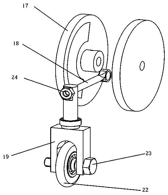
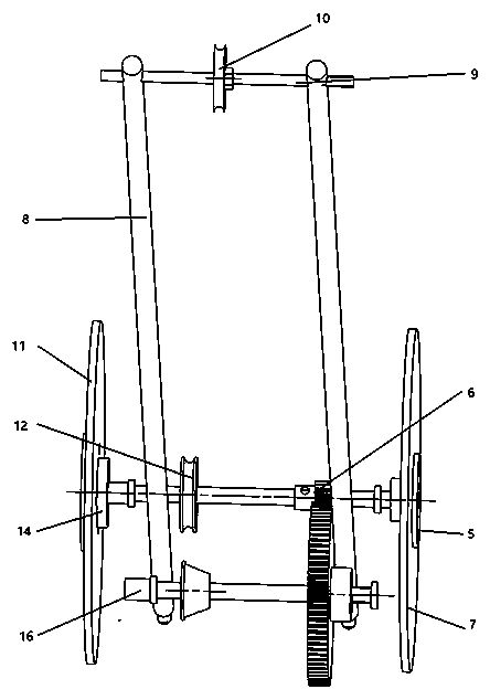
[0018] see figure 1 As shown, the S-type magnetic steering carbon-free trolley includes a frame, a driving device, a transmission device and a magnetic steering device.

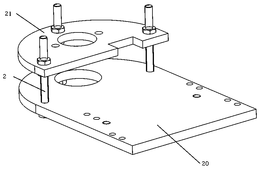
[0019] see figure 1 , figure 2 As shown, the structure of the vehicle frame is tower-shaped, and the vehicle frame includes a lower base plate 20, an upper base plate 21, an adjusting bolt 2, a vertical bearing seat 3, a horizontal bearing seat 1, and a weight suspension rod 8. The weight suspension rod 8 is installed on the middle part of the lower base plate 20 through threaded connection, the upper base plate 21 is installed on the front end of the lower base plate through three sets of adjusting bolts 2, the horizontal bearing seat 1 is fixed on the upper base plate 21 by two bolts, and the two sides of the middle part of the lower base plate 20 Vertical bearing block 3 is installed with screw connection mode with rear both sides.

[0020] see figure 1 , image 3 As shown, the drive device includes:...


PUM


Abstract

The invention relates to a carbon-free vehicle zigzagging in variable distance. The vehicle includes a vehicle frame, a driving device and a magnetic steering device. The magnetic steering device is installed on a driving shaft. Two semicircular magnets identical in shape but opposite in polarity are embedded in two disc-shaped magnet brackets respectively, and the magnet brackets are totally staggered and fixed to the driving shaft. The magnet brackets achieve periodical change of a magnetic field through rotation of the driving shaft to control the vehicle to steer. The vehicle frame is internally provided with an upper chassis mechanism and a lower chassis mechanism. The vehicle can achieve change of the distance between an upper chassis and a lower chassis by adjusting adjustment bolts, and therefore the gravity center of the vehicle is changed. The steering mechanism of the vehicle is simple, the in-vehicle space is greatly saved, and friction is significantly reduced at the sametime; the energy is saved, and meanwhile the mechanical performance of the vehicle is further improved. The upper and lower chassis mechanisms can freely adjust the gravity center of the vehicle, correspondingly the stability of the vehicle is improved, and a series of problems that the vehicle is likely to turn over and slip due to large inertia of the vehicle are solved.

Description

technical field [0001] The invention relates to a carbon-free trolley, in particular to a racing carbon-free trolley based on a magnetic steering mechanism and S-shaped walking, belonging to the technical field of carbon-free trolleys. Background technique [0002] A racing car without carbon, requirements: design a three-wheeled car with continuous obstacle avoidance function using 4J gravitational potential energy as the only energy source. The energy of 4J is obtained by dropping 400mm of 1Kg standard weight, and the allowable error value is ±2mm. The width of the track is 200mm, and a nylon rod with a diameter of 20mm and a height of 200mm is placed every 700mm to 1300mm along the center line of the track from the starting point. If the interval between the first section is 700mm, the second section is 1300mm, with a cycle of 2000mm. The racing car can automatically bypass obstacles on the track when it is moving forward, and the weight must not fall from the car durin...

Claims


Application Information

Patent Timeline
Patent Type & Authority Applications(China)
IPC IPC(8): A63H17/00A63H17/26A63H29/08A63H31/08
Inventor 郝伟张哲杜雄梓侯俊才
Owner NORTHWEST A & F UNIV
Learn More