Purification device unit and purification device

A purification device and housing technology, which is applied in chemical instruments and methods, dispersed particle filtration, gas treatment, etc., can solve the problems of short network disk cleaning and maintenance cycle, network disk blockage, etc., to reduce energy consumption and smoke exhaust resistance , the effect of reducing the hidden danger of fire

Pending Publication Date: 2018-06-05
林德祥
View PDF7 Cites 4 Cited by
  • Summary
  • Abstract
  • Description
  • Claims
  • Application Information

AI Technical Summary

Problems solved by technology

[0005] The first object of the present invention is to provide a purification device unit, which can not only solve the problems that the network disk is easily blocked by oily smoke or other polluted exhaust gas, easily produces fire hazards, and the cleaning and maintenance cycle of the network disk is short, it can also make some The oily fume detached from the filter plate enters the sec...

Method used


Image

  • Purification device unit and purification device
  • Purification device unit and purification device
  • Purification device unit and purification device

Examples


Embodiment 1

[0055] The purification device unit provided by the present invention is mainly used in the fields of purification and filtration of industrial flue gas and kitchen oil fume. In this embodiment, cooking fume is taken as an example for illustration.

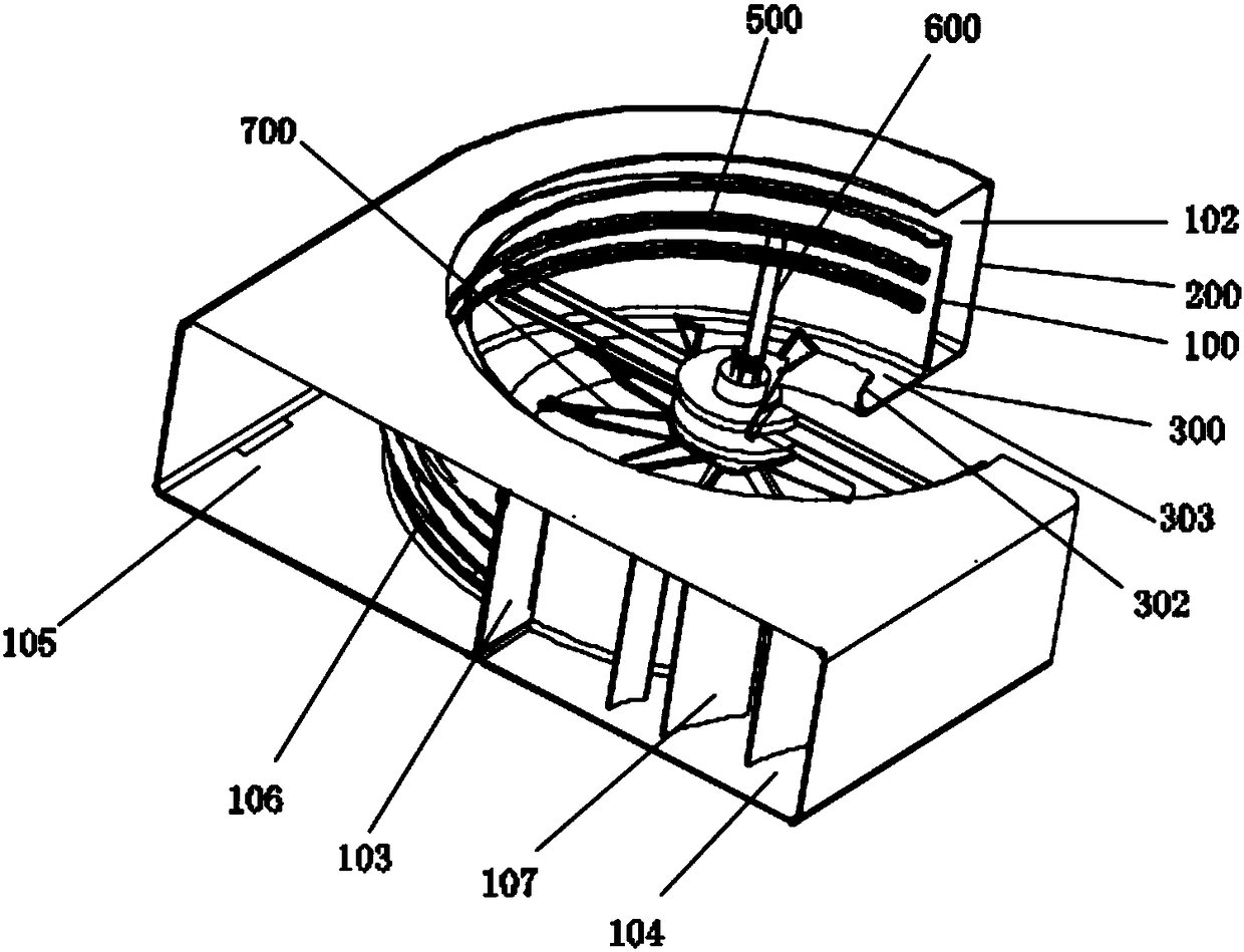
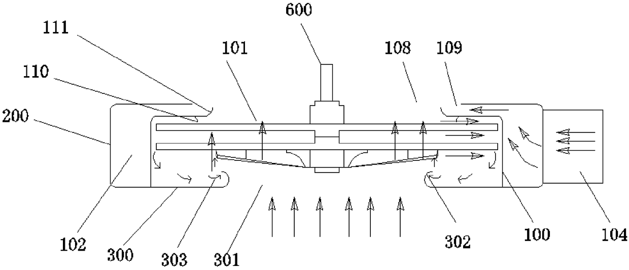
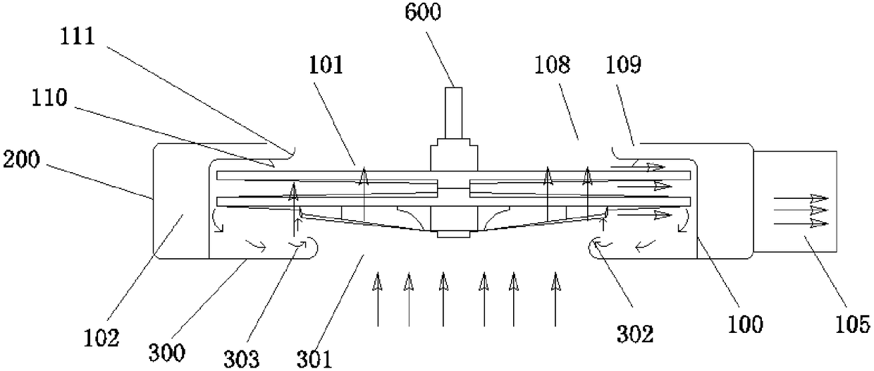
[0056] in, figure 1 A schematic diagram of the three-dimensional structure of the purification device unit provided by Embodiment 1 is shown; figure 2 It shows a schematic structural view of the purification device unit provided by Embodiment 1 at a first viewing angle (in which the air inlet channel is shown in the figure); image 3 It shows a schematic structural diagram of the purification device unit provided by Embodiment 1 at a second viewing angle (in which the air outlet channel is shown in the figure), where the arrows in the drawings of this application all point to the direction of flue gas flow.

[0057] Please refer to Figure 1-Figure 3 As shown; the purification device unit provided in the embodiment of the pre...

Embodiment 2

[0105] A purification device provided in this embodiment includes a gas collection hood 50 and at least one purification device unit provided in Embodiment 1 provided on the gas collection hood 50 .

[0106] like Figure 15 and Figure 16 Shown, where the arrows in the drawings point to the direction of flue gas flow. During specific implementation, the purifying device unit is provided with two, and for the convenience of explanation, the two purifying device units are labeled respectively, wherein the air outlet passage 105 of the first purifying device unit 10 is connected with the air inlet of the second purifying device unit 20 The passage 104 communicates with the auxiliary purification device 30 , and the air inlet passage 104 of the first purification device unit 10 communicates with the air outlet passage 105 of the second purification device unit 20 through the auxiliary purification device 30 .

[0107] The flue gas coarsely filtered by the first purification devi...


PUM

PropertyMeasurementUnit
Diameteraaaaaaaaaa

Abstract

The invention provides a purification device unit and a purification device, and belongs to the field of purification equipment. The purification device unit comprises a casing assembly and a filtering assembly, wherein the casing assembly comprises a first casing and a second casing; a second smoke gas passage is formed between the first casing and the second casing; the second smoke gas passageis provided with an air inlet passage and an air outlet passage separated by a separation plate; an air outlet is formed in a casing wall, corresponding to the air outlet passage, of the first casing;the filtering assembly comprises a filtering screen disc, a transmission element and a flow guide impeller; the flow guide impeller can guide the airflow introduced into the filtering screen disc tothe radial direction of the filtering screen disc so that the airflow can be cut in the peripheral region near the filtering screen disc. The purification device unit solves the problem that the center region of the filtering screen disc can be easily blocked; partial smoke gas disengaged from the purification screen disc can enter the second smoke gas passage through a first smoke gas passage andis then filtered; the filtering efficiency is improved. The purification device comprises at least one purification device unit.

Description

technical field [0001] The invention relates to the field of purification equipment, in particular to a purification device unit and a purification device. Background technique [0002] At present, PM2.5 is mainly affected by two aspects, one is climate factors, and the other is pollutant emissions. Gas purification equipment plays a role in gas filtration, but there are many problems in the purifiers currently on the market, resulting in high cost of air pollution control, general effect and difficult to maintain stability. [0003] For example, high-voltage static electricity, wet type, mechanical filter type and activated carbon type have a large amount of maintenance, complex structure, high operating cost, unstable purification efficiency and short service life, and a dynamic centrifugal purifier on the market, one of which is a radial wire wound Through the high-speed rotation of the mesh disk, the radial wires continuously cut and hit the oil fume or other exhaust ga...

Claims


Application Information

Patent Timeline
IPC IPC(8): B01D46/00B01D53/32
CPCB01D46/0056B01D53/32B01D2258/0283
Inventor 林德祥
Owner 林德祥
Why Eureka
Try Eureka