Cleaning device for cylinder sleeves of engines

A technology for cleaning device and engine cylinder, applied in the field of machinery, can solve problems such as difficulty in cylinder liner, inability to meet cleaning requirements, etc., and achieve the effect of convenient collection

Inactive Publication Date: 2018-06-05
沈阳元生鑫达科技有限公司
View PDF0 Cites 1 Cited by
  • Summary
  • Abstract
  • Description
  • Claims
  • Application Information

AI Technical Summary

Problems solved by technology

[0003] The current cleaning method is to place all cylinder liners in an ultrasonic cleaner for ultrasonic cleaning or to stack them on a platform and then spray them. The specific method is to place all cylinder liners in an ultrasonic cleaner for ultrasonic cleaning. Corresponding cleaning requirements, but it is much more difficult to clean a large number of cylinder liners at the same time, and cannot meet the corresponding cleaning requirements

Method used


Image

  • Cleaning device for cylinder sleeves of engines

Examples


Embodiment Construction

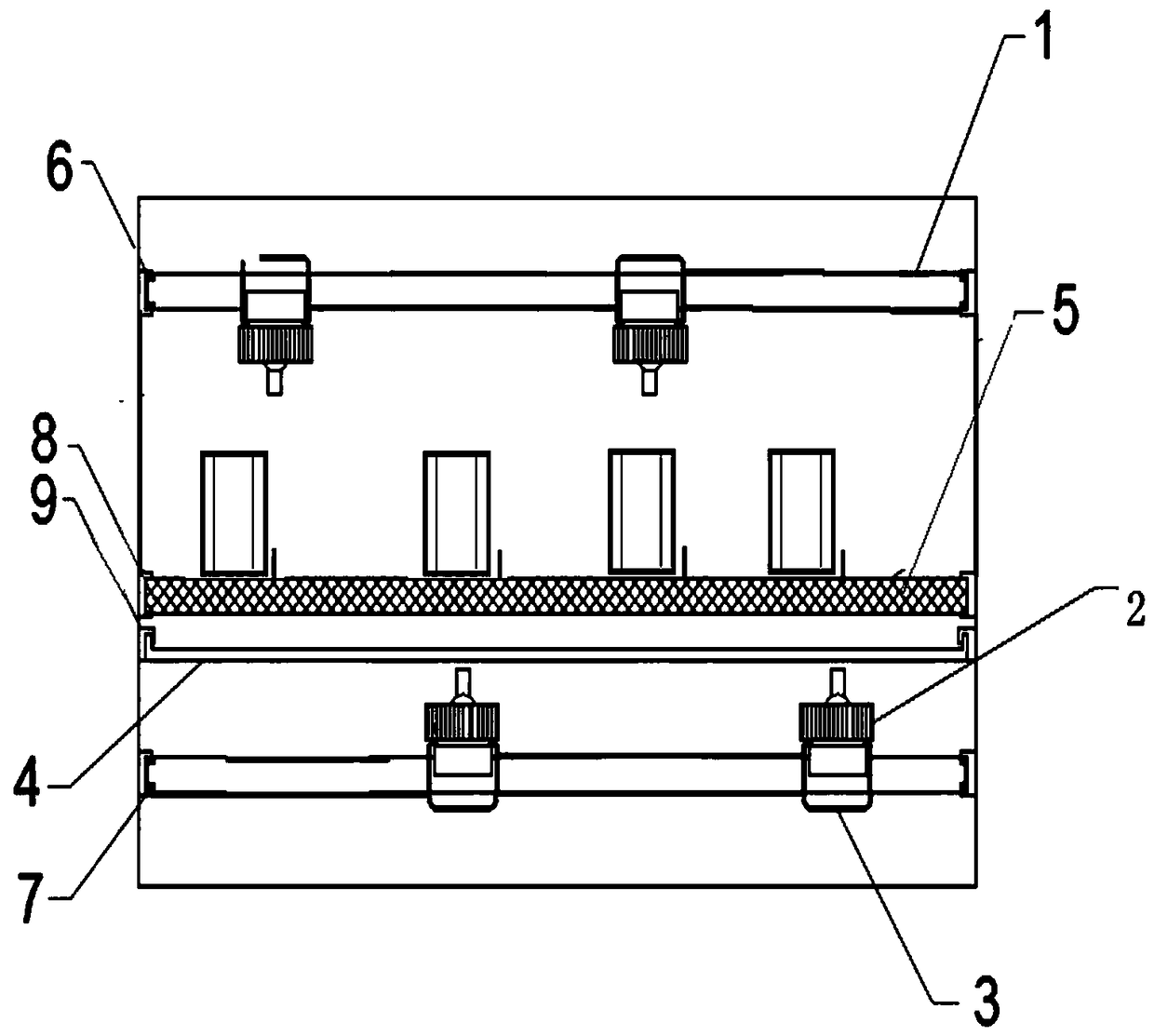
[0020] An automatic cylinder liner cleaning device, such as figure 1 As shown, it includes a spraying device and an automatic transmission device, and the described spraying device includes a spraying pipe 1, nozzles 2 distributed on the spraying pipe 1 and pipe clamps 3 for fixing the nozzles 2; the automatic The transmission device includes a conveyor belt 4, and the spray pipes 1 are arranged on the upper and lower sides of the conveyor belt 4 respectively. There is also a baffle 5 between them, and the conveyor belt 4 and the baffle 5 are all mesh structures.

[0021] The nozzle upper mounting frame 6 is located inside the cleaning device, and the upper spraying pipe 1 is slidable in the nozzle mounting frame 6; the nozzle lower mounting frame 7 is located inside the cleaning device, and the lower spraying pipe 1 It can slide in the installation frame 7 under the nozzle; the limiting groove A8 is located inside the cleaning device, and the baffle plate 5 is slidable in th...


PUM


Abstract

The invention belongs to the field of machines, and relates to a cleaning device, particularly relates to a cleaning device for cylinder sleeves of engines. According to the cleaning device, the modethat spraying pipelines are arranged up and down correspondingly is adopted, the spraying pipelines are arranged in a staggered mode, and the spraying directions of nozzles arranged on the spraying pipelines point to a conveying belt so that two sides and insides of the cylinder sleeves on the conveying belt can be cleaned; and a baffle plate arranged between the upper spraying pipeline and the conveying belt can play a role in shielding the cylinder sleeves blown by the nozzles, so that the relative positions of the cylinder sleeves are prevented from shifting. The cleaning device comprises aspraying device and an automatic conveying device, wherein the spraying device comprises the spraying pipeline, the nozzles and pipe clamps, wherein the nozzles are distributed on the spraying pipelines, and the pipe clamps are used for fixing the nozzles; and the automatic conveying device comprises the conveying belt, the spraying pipelines are arranged on the upper side and the lower side of the conveying belt respectively, the spraying directions of the spraying nozzles point to the conveying belt, the baffle plate is arranged between the upper spraying pipeline and the conveying belt, and the conveying belt and the baffle plate are of a net structure.

Description

technical field [0001] The invention belongs to the field of machinery and relates to a cleaning device, in particular to a cleaning device for an engine cylinder liner. Background technique [0002] The cylinder liner is an important part of the engine. During the engine assembly process, the cleanliness of the cylinder liner is very strict. If the cylinder liner is polluted during the assembly process, it will cause cylinder scuffing. Cylinder scuffing refers to the phenomenon that the piston assembly and the working surface of the cylinder interact violently (generated from friction), resulting in excessive wear, roughening, scratches, abrasions, cracks or seizures on the working surface. Cylinder scuffing is a phenomenon that occurs when there is lubrication Different degrees of adhesive wear under different conditions. When the cylinder is pulled lightly, the cylinder liner and piston assembly will be damaged. Major accidents. Therefore, it is particularly important to...

Claims


Application Information

Patent Timeline
Patent Type & Authority Applications(China)
IPC IPC(8): B08B9/02B08B13/00
CPCB08B9/02B08B3/022B08B13/00
Inventor 葛程程李富佳李静
Owner 沈阳元生鑫达科技有限公司
Why Eureka
Try Eureka