A friction stir welded part

A technology of friction stir welding and friction stir welding, which is applied in welding equipment, non-electric welding equipment, metal processing equipment, etc., can solve problems such as welding defects, influence of welding line speed, and damage to the inclination control axis, so as to improve service life and reduce The effect of friction, an effect

Active Publication Date: 2020-04-10
广东柳泰焊接科技有限公司
View PDF7 Cites 0 Cited by
  • Summary
  • Abstract
  • Description
  • Claims
  • Application Information

AI Technical Summary

Problems solved by technology

[0004] The purpose of the present invention is to provide a friction stir welding component to solve the above-mentioned background technology that often requires multi-axis linkage to control the inclination angle. The calculation and control time of the equipment is relatively long. For complex curve welds, especially curvature changes As far as welding seams are concerned, the welding line speed will be affected by the system calculation and control adjustment time, which often leads to excessive heat input of the weld here, resulting in welding defects, and when the inclination angle is generated, the stirring head will squeeze the inclination angle The control shaft, long-term use will cause damage to the tilt control shaft, affecting the use of the problem

Method used


Image

  • A friction stir welded part
  • A friction stir welded part
  • A friction stir welded part

Examples


Embodiment Construction

[0022] The following will clearly and completely describe the technical solutions in the embodiments of the present invention with reference to the accompanying drawings in the embodiments of the present invention. Obviously, the described embodiments are only some, not all, embodiments of the present invention. Based on the embodiments of the present invention, all other embodiments obtained by persons of ordinary skill in the art without making creative efforts belong to the protection scope of the present invention.

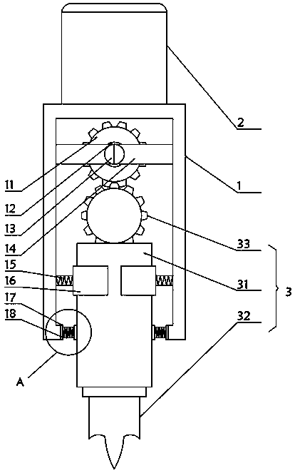
[0023] see Figure 1-3 , the present invention provides a technical solution:

[0024] A friction stir welded component such as figure 1 As shown, it includes an inclination control shaft 1, a main motor 2 installed on the top of the inclination control shaft 1, and a friction stir welding tool 3 installed inside the inclination control shaft 1. The interior of the inclination control shaft 1 is equipped with an active tooth 11, and the active tooth 11 A rot...


PUM


Abstract

The invention relates to the technical field of welding equipment, in particular to a friction stir welding part. The friction stir welding part comprises a dip angle control shaft, a main motor and afriction stir welding tool, wherein the main motor is arranged on the top of the dip angle control shaft, and the friction stir welding tool is arranged in the dip angle control shaft. A driving gearis driven to rotate through a rotating motor, and a transmission gear rotates in the reverse direction along with the rotation of the driving gear; the problem that the welding defect is caused due to the fact that existing equipment is relatively long in calculation and control time is solved, rapid switching of dip angles is achieved, and the welding effect is improved; the interior of the dipangle control shaft is protected through the movement of a first spring and a clamping ring, the friction in the dip angle control shaft is reduced when a connecting shaft is inclined, and the overallservice life is prolonged; through attachment of an extruding plate and the connecting shaft, supporting and buffering of extrusion force are conducted through a fixing plate and a second spring, sothat the friction force of the connecting shaft at the open end during inclination is reduced, and the overall service life is prolonged.

Description

technical field [0001] The invention relates to the technical field of welding equipment, in particular to a friction stir welding component. Background technique [0002] The friction stir welding process is the most eye-catching welding method since the advent of laser welding. Its appearance will lead to major changes in the connection technology of non-ferrous metals such as aluminum alloys. Welding aluminum alloys with friction stir welding has achieved good results. In the process of friction stir welding, in order to avoid or reduce the occurrence of defects such as tunnels, holes, and grooves, the axis of the friction stir welding tool is not directly perpendicular to the surface of the workpiece during welding in general, but between the tangent of the weld trajectory and the surface of the workpiece. The plane formed by the lines has an inclination angle of 3~5°. In order to achieve this inclination following control, the traditional friction stir welding equipm...

Claims


Application Information

Patent Timeline
Patent Type & Authority Patents(China)
IPC IPC(8): B23K20/12B23K20/26
CPCB23K20/1245
Inventor 唐远金徐安莲
Owner 广东柳泰焊接科技有限公司
Why Eureka
Try Eureka