
A banknote storage unit

A storage device and a technology for banknotes, which can be applied to banknote processing equipment, processing coins or valuable banknotes, and devices for accepting coins, etc., and can solve problems such as increasing costs.

Active Publication Date: 2018-06-05
INNOVATIVE TECH LTD
View PDF10 Cites 0 Cited by
  • Summary
  • Abstract
  • Description
  • Claims
  • Application Information

AI Technical Summary

Problems solved by technology

However, these approaches are avoided due to the complex differential motor control they require and the additional cost of using more than one motor

Method used


Image

  • A banknote storage unit
  • A banknote storage unit
  • A banknote storage unit

Examples


Embodiment Construction

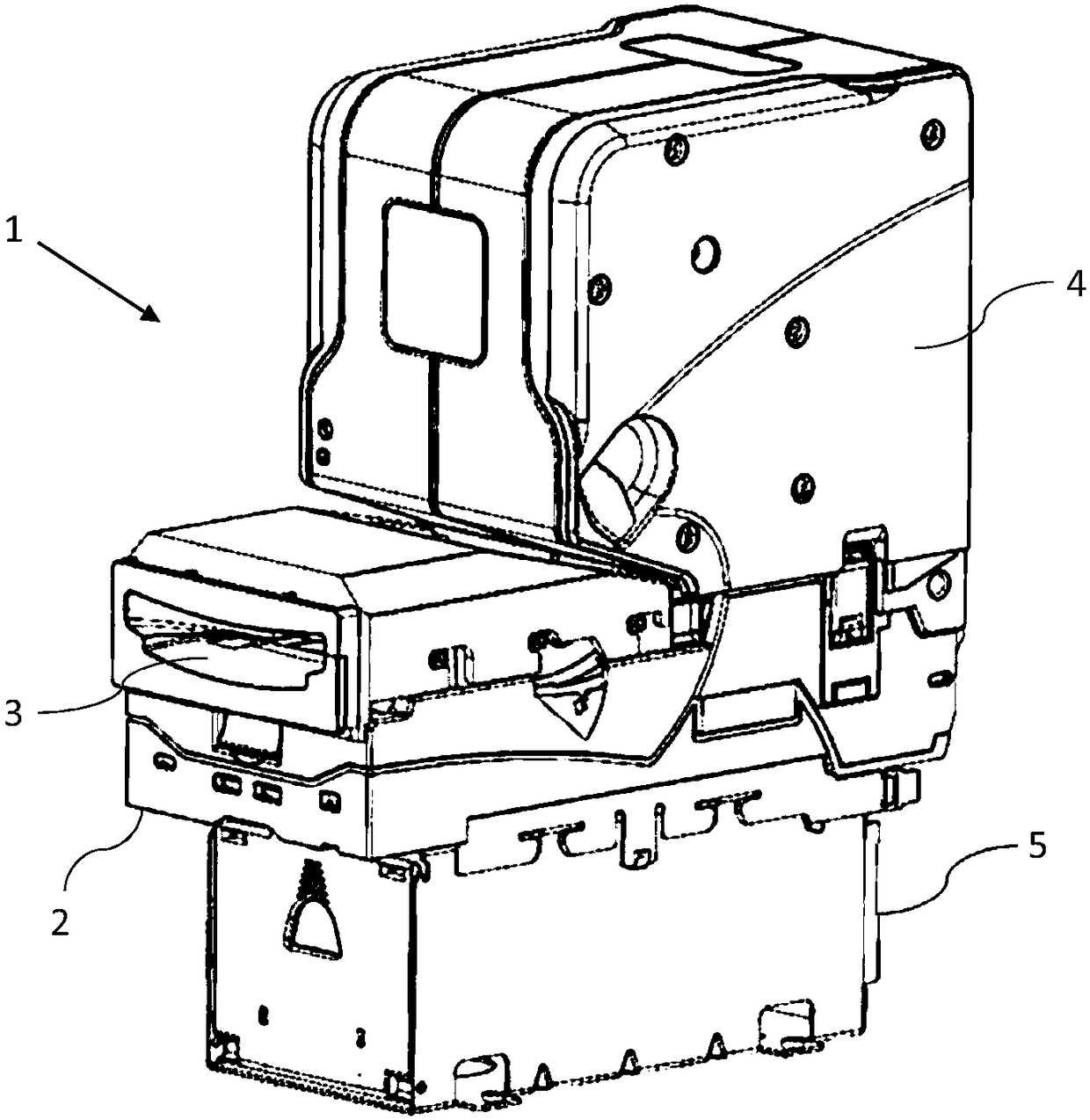
[0030] like figure 1 As shown, the banknote recycler 1 includes a banknote transport and validator mechanism 2 having a banknote input / output aperture 3 , a cash box 5 and a banknote storage device 4 .

[0031] The banknotes loaded into the banknote circulator 1 through the input / output opening 3 are checked for authenticity by the banknote transport and validator mechanism 2 . Rejected banknotes are returned to the user through the input / output aperture 3, while acceptable banknotes are either transferred to a cash drawer 5 for subsequent collection, or they are conveyed to a banknote storage facility 4 for temporary storage to be dispensed on demand at a later time .

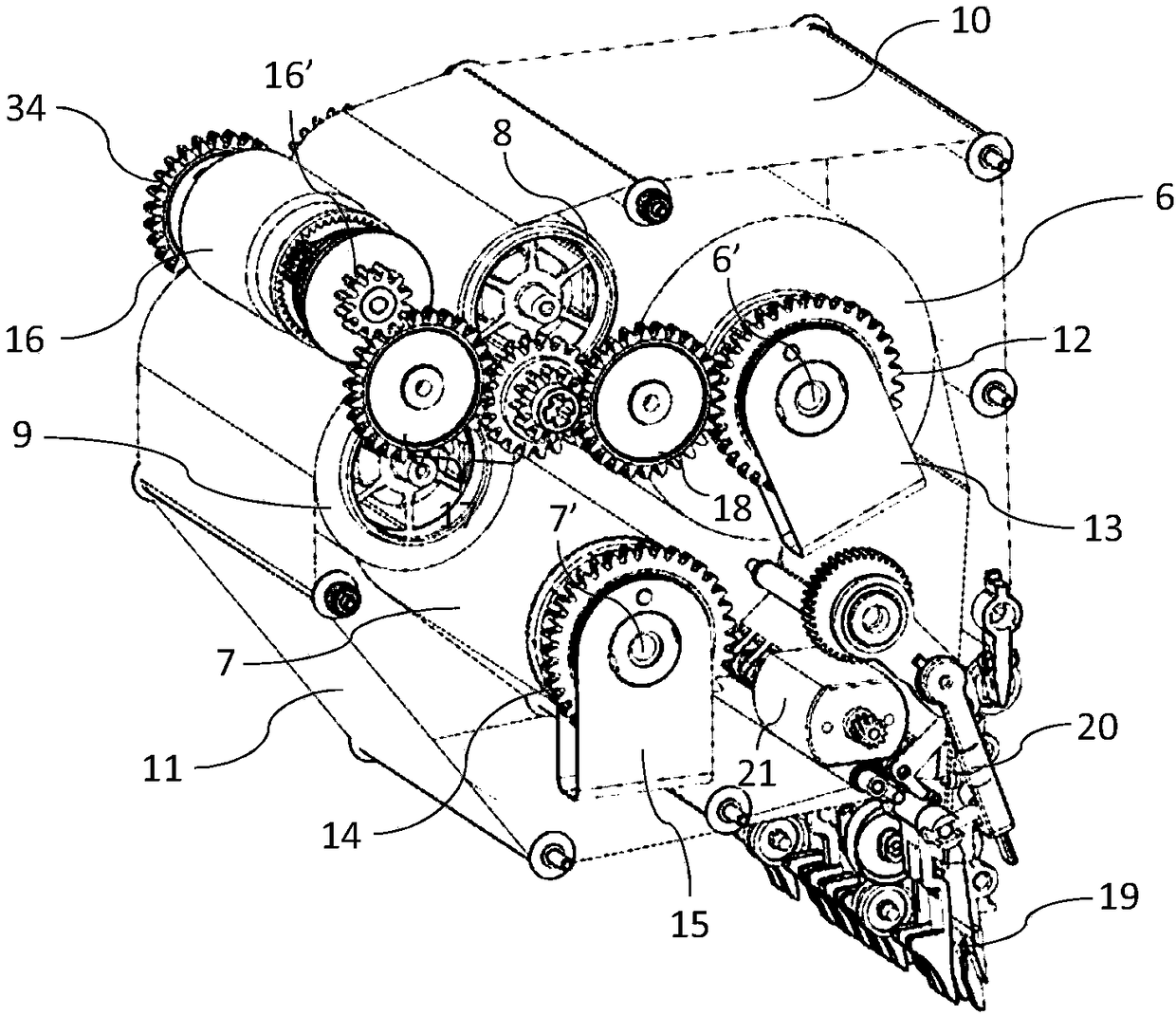
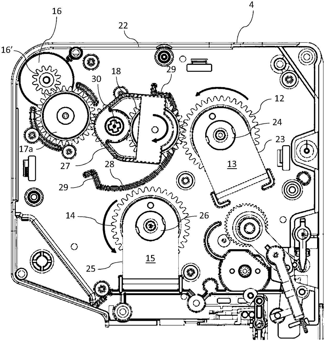
[0032] Banknotes determined to be acceptable and destined for the banknote storage device 4 are routed through a validator mechanism inside the banknote transport path (not shown) from which the banknote enters the banknote storage device 4 via the banknote input / output path 19 (see figure 2 ).

[0033] r...


PUM


Abstract

A banknote storage unit comprising: a first tape reel banknote storage device; a second tape reel banknote storage device; and a drive transmission means pivotable between engagement with said first tape reel banknote storage device and engagement with said second tape reel banknote storage device.

Description

technical field [0001] The present invention relates to devices capable of receiving, distributing and storing valuable sheets or documents. In particular, the invention relates to a banknote storage device which can be used in combination with a banknote transport and verification device to form a banknote recycler known in the art. Background technique [0002] In conventional banknote storage devices, banknotes are stored between and supported by opposing strips of plastic strapping which in turn is coiled around a storage drum or roll. [0003] Typically, banknote storage devices include two storage drums and a further pair of supply drums. In operation, it is known to store banknotes continuously between the windings of the tape on one or two storage drums, said drums being driven to wind and unwind the tape from the storage drum to the supply drum, vice versa. [0004] A problem with conventional banknote storage devices is that when the belt is being wound or unwou...

Claims


Application Information

Patent Timeline
IPC IPC(8): B65H1/12B65H1/26
CPCB65H1/12B65H1/26B65H29/006B65H2220/09B65H2301/41912B65H2301/41924B65H2403/54B65H2403/722B65H2403/725B65H2403/73B65H2701/1912G07D2211/00G07D11/12G07D11/18G07D11/50G07D11/16B65H2301/4191G07D11/24
Inventor M·萨克菲尔德
Owner INNOVATIVE TECH LTD
Learn More