Template structure for reserving equipment basic embedded bolt hole in cast-in-place concrete
A technology of concrete foundation and equipment foundation, which is applied to the preparation of building components on site, formwork/formwork/work frame, building construction, etc. Problems such as disassembly and cleaning
- Summary
- Abstract
- Description
- Claims
- Application Information
AI Technical Summary
Problems solved by technology
Method used
Image
Examples
Embodiment 1
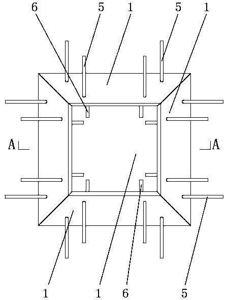
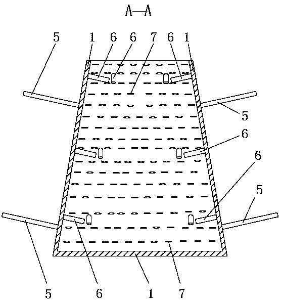
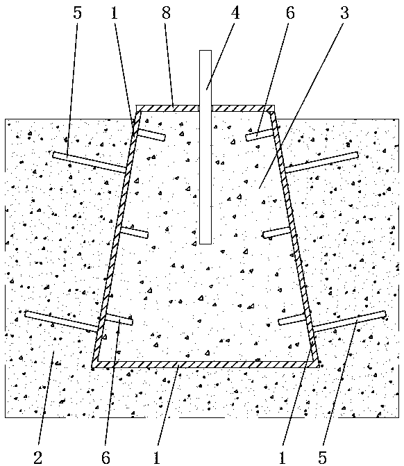
[0020] Such as Figures 1 to 3 As shown, the formwork structure used to reserve embedded bolt holes for equipment foundation in cast-in-place concrete includes a reserved hole box composed of fixed connections of steel plates 1 at the bottom and surroundings, and the thickness of steel plates 1 is 5mm. The ground, bottom and surrounding steel plates 1 are fixedly connected by welding, which is convenient and quick to assemble through welding, and the overall structural strength is good. The reserved hole box is fixedly installed in the concrete foundation 2, and the inside of the reserved hole box is used for pouring internal concrete 3. The concrete 3 is used to fix the anchor bolts 4. Specifically, the reserved hole box is a conical body with a small upper opening and a large lower opening, surrounded by four steel plates 1 welded, the upper opening and the lower opening are both rectangular, and the bottom plate and The lower ends of the four steel plates 1 are welded and f...
Embodiment 2
[0022] Such as Figures 1 to 3 As shown, on the basis of embodiment 1, the outer wall of the steel plate 1 around the reserved hole box is fixedly connected to the outer pull-out rod 5 by welding, the outer pull-out rod 5 is threaded steel, and the outer pull-out rod 5 is fixed to the concrete foundation 2 connection, improve the pullout performance of the reserved hole box, so that it can be firmly installed in the concrete foundation 2, and further, one end of the outer pullout rod 5 is fixedly connected with the outer wall of the steel plate 1 around the reserved hole box by welding, and the other end Extending into the concrete foundation 2 and upturning, so that one end of the outer pull-out rod 5 is lower than the other end, forming a barb-like pull-out structure, which further improves the pull-out performance of the reserved hole box and ensures that the reserved hole box It is installed in the concrete foundation 2 more stably, so that the reserved hole box and the co...
Embodiment 3
[0024] Such as Figures 1 to 3 As shown, on the basis of Example 1, the inner wall of the reserved hole box is fixedly provided with an inner pull-out rod 6 and / or an anti-slip pattern 7, the inner pull-out rod 6 is welded and fixed to the inner wall, and the anti-slip pattern 7 can be integrated with the steel plate 1 Forming, the inner pull-out rod 6 is screw steel, that is, the inner pull-out rod 6 or the anti-skid pattern 7 can be fixed separately on the inner wall, or the inner pull-out rod 6 and the anti-skid pattern 7 can be fixed on the inner wall at the same time, and the internal concrete can be lifted 3's anti-pullout performance, so that the internal concrete 3 is firmly arranged in the reserved hole box, and further, when the inner anti-pullout rod 6 is fixedly installed on the inner wall, one end of the inner anti-pullout rod 6 and the steel plate around the reserved hole box The inner wall of 1 is fixedly connected, and the other end can extend into the inner co...
PUM
 Abstract
Description
Claims
Application Information
 - R&D
- Intellectual Property
- Life Sciences
- Materials
- Tech Scout
- Unparalleled Data Quality
- Higher Quality Content
- 60% Fewer Hallucinations
Browse by: Latest US Patents, China's latest patents, Technical Efficacy Thesaurus, Application Domain, Technology Topic, Popular Technical Reports.
© 2025 PatSnap. All rights reserved.Legal|Privacy policy|Modern Slavery Act Transparency Statement|Sitemap|About US| Contact US: help@patsnap.com


