Radial and defection combined loading bench test tool for traction bar

A combined loading and bench test technology, applied in the direction of measuring devices, vehicle testing, mechanical component testing, etc., can solve problems such as damage to the bench actuator, actuator damage, difficult deflection force, etc., to ensure the test. The effect of accuracy, low manufacturing cost, safe and reliable work

Inactive Publication Date: 2018-06-05
HENAN VOCATIONAL & TECHN COLLEGE OF COMM
View PDF4 Cites 6 Cited by
  • Summary
  • Abstract
  • Description
  • Claims
  • Application Information

AI Technical Summary

Problems solved by technology

[0003] At present, most of the bench tests of the thrust rod assembly are in the single-item loading stage, but the bench test requires that the force state of the thrust rod should be consistent with that of the real vehicle, which requires that the bench test apply radial and deflection forces to the thrust rod assembly at the same time, and ensure that The radial force can only be along the direction of the thrust rod shaft. At present, most test benches use radial actuators. The radial deformation of the thrust rod produces a large bending moment, which will cause great damage to the actuator, and it will be damaged in long-term tests. Bench actuator, and it is difficult to apply deflection force

Method used


Image

  • Radial and defection combined loading bench test tool for traction bar

Examples


Embodiment 1

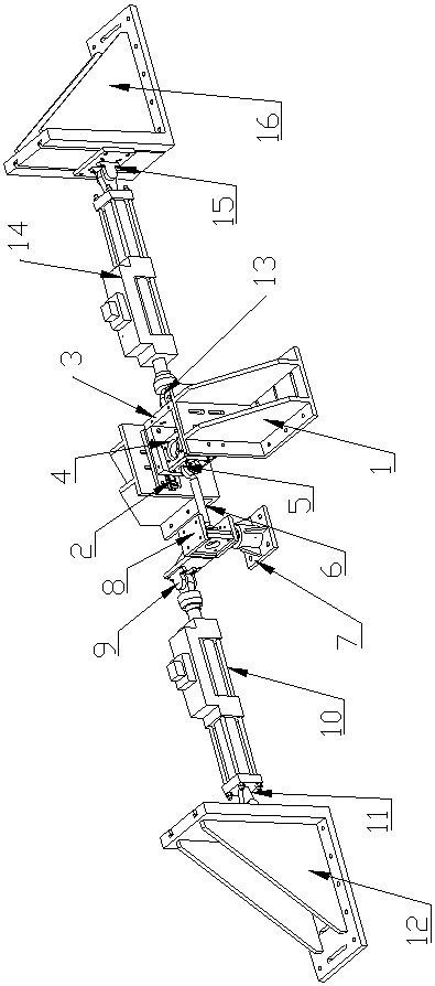
[0015] Such as figure 1 As shown, a thrust rod radial plus deflection combined loading bench test tooling, it includes a slide rail reaction force support 1, the rear side of the slide rail reaction force support 1 is connected with a linear slide rail 2, the described The linear slide rail 2 is connected with a fixed frame 3, and the inside of the fixed frame 3 is connected with a fixed block 4, and the left side of the fixed block 4 is connected with a ball hinge connecting block 5, and the ball hinge connecting block 5 is hinged with a thrust rod 6, the other end of the thrust rod 6 is hinged with a rotating base 7, the upper part of the rotating base 7 is connected with a deflection tool 8, and the left side of the deflection tool 8 is connected with a deflection Actuator ball joint B9, the deflection actuator ball joint B9 is hinged with a deflection actuator 10, the left end of the deflection actuator 10 is hinged with a deflection actuator ball hinge A11, and the deflec...

Embodiment 2

[0018] Such as figure 1 As shown, a thrust rod radial plus deflection combined loading bench test tooling, it includes a slide rail reaction force support 1, the rear side of the slide rail reaction force support 1 is connected with a linear slide rail 2, the described The linear slide rail 2 is connected with a fixed frame 3, and the inside of the fixed frame 3 is connected with a fixed block 4, and the left side of the fixed block 4 is connected with a ball hinge connecting block 5, and the ball hinge connecting block 5 is hinged with a thrust rod 6, the other end of the thrust rod 6 is hinged with a rotating base 7, the upper part of the rotating base 7 is connected with a deflection tool 8, and the left side of the deflection tool 8 is connected with a deflection Actuator ball joint B9, the deflection actuator ball joint B9 is hinged with a deflection actuator 10, the left end of the deflection actuator 10 is hinged with a deflection actuator ball hinge A11, and the deflec...


PUM


Abstract

The invention relates to a radial and deflection combined loading bench test tool for a traction bar. The radial and deflection combined loading bench test tool comprises a slide rail counterforce support, wherein the slide rail counterforce support is connected with a linear slide rail; the linear slide rail is connected with a fixed frame; a fixed block is connected to the interior of the fixedframe and connected with a spherical hinge connection block; the spherical hinge connection block is hinged to the traction bar; the traction bar is hinged to a rotary base; a defection tool is connected to the upper part of the rotary base; a deflection actuator spherical hinge B is connected to the left side surface of the deflection tool and hinged to a deflection actuator; the deflection actuator is hinged to a deflection actuator spherical hinge A; the deflection actuator spherical hinge A is connected with an actuator counterforce support A; a radial actuator spherical hinge B is hingedto the right side surface of the fixed frame; the right end of the radial actuator spherical hinge B is connected with a radial actuator; the right end of the radial actuator is hinged to a radial actuator spherical hinge A; and the right side surface of the radial actuator spherical hinge A is connected with an actuator counterforce support B. The radial and deflection combined loading bench testtool for the traction bar has the advantages of reasonable structure, accurate test, high safety and reliability, excellent adaptability and low manufacture cost.

Description

technical field [0001] The invention belongs to the technical field of automobile equipment, and in particular relates to a thrust rod radial plus deflection combined loading bench test fixture. Background technique [0002] In recent years, the market has reported that there are more and more problems such as deformation and fracture of the thrust shaft of the bus, and cracking and crushing of the rubber of the ball joint bushing. And component manufacturers attach great importance to it. In order to prevent unqualified thrust rod products from entering the market, early judgment and effective improvement are the most effective methods. It is still the most direct and convenient in the industry to judge whether the thrust rod assembly is qualified through the thrust rod assembly bench test. , the most effective judgment method. [0003] At present, most of the bench tests of the thrust rod assembly are in the single-item loading stage, but the bench test requires that the ...

Claims


Application Information

Patent Timeline
Patent Type & Authority Applications(China)
IPC IPC(8): G01M13/00G01M17/007
CPCG01M13/00G01M17/007
Inventor 徐硕
Owner HENAN VOCATIONAL & TECHN COLLEGE OF COMM
Why Eureka
Try Eureka