
A method and device for super-resolution fluorescence lifetime imaging based on parallel detection

A technology of super-resolution fluorescence and imaging devices, which is applied in measurement devices, fluorescence/phosphorescence, and material analysis through optical means, can solve the problems of low photon detection and counting efficiency, slow imaging speed, etc., and achieve improved lifetime imaging speed, Improvement of imaging speed and signal-to-noise ratio

Active Publication Date: 2020-08-11
ZHEJIANG UNIV
View PDF9 Cites 0 Cited by
  • Summary
  • Abstract
  • Description
  • Claims
  • Application Information

AI Technical Summary

Problems solved by technology

Lifetime measurement based on confocal system and TCSPC counting device is a kind of time-domain lifetime imaging method, which can provide better lifetime imaging resolution, and can flexibly measure long and short-lived samples with various dynamic ranges, but this Due to the influence of the detector and counter dead time, the detection and counting efficiency of photons is low, so the imaging speed is very slow, which is also the biggest disadvantage of this method

Method used


Image

  • A method and device for super-resolution fluorescence lifetime imaging based on parallel detection
  • A method and device for super-resolution fluorescence lifetime imaging based on parallel detection
  • A method and device for super-resolution fluorescence lifetime imaging based on parallel detection

Examples


Embodiment Construction

[0048] The present invention will be described in detail below in conjunction with the embodiments and accompanying drawings, but the present invention is not limited thereto.

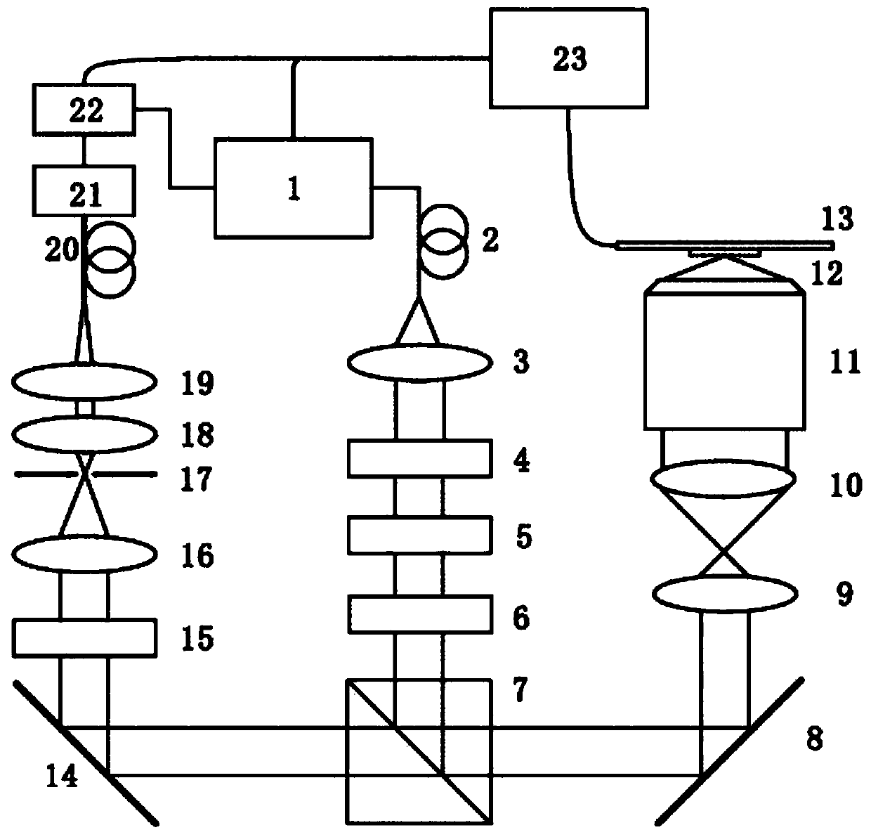
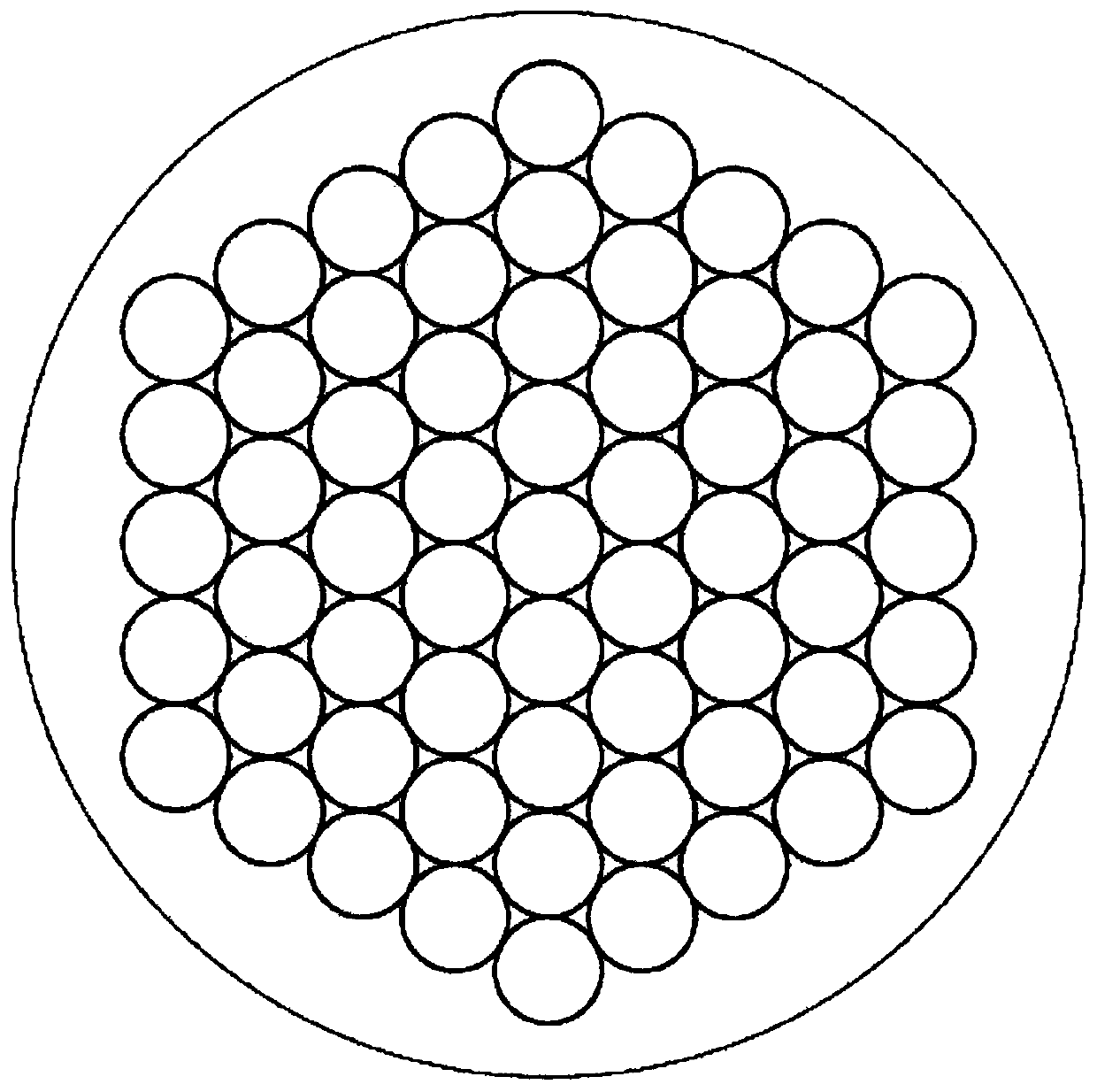
[0049] Such as figure 1 The shown super-resolution fluorescence lifetime imaging device based on parallel detection includes: laser light source 1, polarization maintaining fiber 2, collimator lens 3, 1 / 4 wave plate 4, 1 / 2 wave plate 5, 1 / 4 wave plate 6 , dichroic mirror 7, mirror 8, scanning mirror 9, field lens 10, high numerical microscope objective lens 11, sample 12, scanning platform 13, mirror 14, narrow-band filter 15, lens 16, aperture stop 17, lens 18 , Converging lens 19, fiber bundle 20, APD array 21, TCSPC array 22 and computer and controller 23.

[0050] The collimating lens 3 , the 1 / 4 wave plate 4 , the 1 / 2 wave plate 5 and the 1 / 4 wave plate 6 are sequentially located on the optical axis of the light beam emitted by the laser light source 1 . The excitation beam is reflected by the ...


PUM


Abstract

The invention discloses a super-resolution fluorescent lifetime imaging device based on parallel detection. The device comprises a light source, wherein exciting light sent by the light source is focused to a sample through a microobjective and signal light sent by the sample is collected, wherein a detection system receiving the signal light comprises a plurality of fiber bundles, a detector array and a time related single photon counter array; the plurality of fiber bundles receive the signal light at the same time; the detector array is provided with a plurality of detectors separately connected to fibers to obtain corresponding light intensity signals; and the time related single photon counter array is provided with time related single photon counters which are separately connected tothe detectors and are synchronized with the pulse of the light source for calculating the fluorescent lifetime and achieving super-resolution fluorescent lifetime imaging. The invention also discloses a super-resolution fluorescent lifetime imaging method based on parallel detection. By means of parallel APD and parallel TCSPC, the imaging resolution is enhanced, and the lifetime imaging speed isalso remarkably improved.

Description

technical field [0001] 本发明属于超分辨显微荧光寿命成像领域,尤其是涉及一种基于并行探测的超分辨荧光寿命成像方法和装置。 Background technique [0002] 光与物质的作用是自然界中最基础的作用过程,尤其是单个原子与单个光子的相互作用是实现光与物质作用的最普遍的元素。而在这个领域,超分辨荧光显微成像一直是生物医学研究的重点,通过对生物分子的特殊标记,荧光光学显微镜在观察亚细胞结构扮演着重要的角色。 [0003] 荧光信息具有四个基本的物理维度,包括强度信息,波长信息(吸收光谱和发射光谱),寿命信息和偏振信息。目前的超分辨显微技术主要集中利用在强度和波长上,包括利用荧光的吸收与发射谱,实现强度上的“开关”调制(STED技术,PALM / STORM技术等),或者利用结构上的强度调制技术包括SIM技术或者饱和SIM技术。而在偏振方面,目前也有不少技术实现偏振解调,获取偏振信息从而实现分辨率的提高。除了这些之外,寿命信息是生物微结构成像方面非常重要的一个信息,荧光寿命成像是一个越来越广泛应用的光谱技术,它能够提供特定的荧光团的定位信息和荧光分子的微环境变化信息,包括许多生物物理、生物化学参数如离子浓度、PH值、氧浓度、折射率、黏性、和温度等,特别的,荧光寿命成像也能够应用于对荧光分子对的荧光共振能量转移(FRET)的探测,能够用于研究蛋白质与细胞的相互动力作用。荧光寿命成像的主要优点在于其成像结果对荧光浓度和聚焦情况并不敏感,因此不需要得到荧光强度即可获取所需的寿命信息。同时荧光寿命成像也可以与共聚焦、STED技术相结合,为生物医学研究提供新的研究手段。 [0004] 目前的荧光寿命成像方式主要有两大类,一类是时域寿命成像方法,另一类是频域寿命成像方法,但两种方法的本质是相同的。频域寿命成像方法更适合对寿命分布呈多指数衰减的样品,而时间寿命成像则适用于更为灵活、大的动态范围和长寿命的样品。基于共聚焦系统和TCSPC计数装置来进行寿命测量是时域寿命成像方法的一种,它能够提供较好的寿命成像分辨率,同时能够灵活的测量各种动态范围的长短寿命样品,但是这种方法由于受到探测器和计数器死程时间的影响,对光子的探测和计数效率较低,因此成像速度很慢,这也是这种方法最大的缺点。 Contents of the inv...

Claims


Application Information

Patent Timeline
Patent Type & Authority Patents(China)
IPC IPC(8): G01N21/64G01N21/01
CPCG01N21/01G01N21/6402
Inventor 匡翠方刘少聪陈友华刘旭李海峰张克奇毛磊
Owner ZHEJIANG UNIV
Learn More