Fluorescence lifetime imaging method and device based on spectrum division technology

A fluorescence lifetime, imaging device technology, applied in spectrometry/spectrophotometry/monochromator, measurement device, fluorescence/phosphorescence, etc. problem, to achieve the effect of speed improvement, fluorescence lifetime imaging speed, and detection efficiency improvement

Pending Publication Date: 2020-12-22
ZHEJIANG UNIV
View PDF1 Cites 2 Cited by
  • Summary
  • Abstract
  • Description
  • Claims
  • Application Information

AI Technical Summary

Problems solved by technology

However, this lifetime system based on confocal and TCSPC counters also has limitations, the most critical being the limitation of imaging speed
Due to the influence of the dead time of the detector and TCSPC, in order to avoid the impact of photon accumulation on the lifetime, the light intensity must be weakened, and at the same time, in order to obtain enough photon numbers to obtain lifetime information, the single-point detection time must be extended. Therefore, the imaging speed is limited, making it difficult to apply to real-time lifetime imaging

Method used


Image

  • Fluorescence lifetime imaging method and device based on spectrum division technology
  • Fluorescence lifetime imaging method and device based on spectrum division technology
  • Fluorescence lifetime imaging method and device based on spectrum division technology

Examples


Embodiment 1

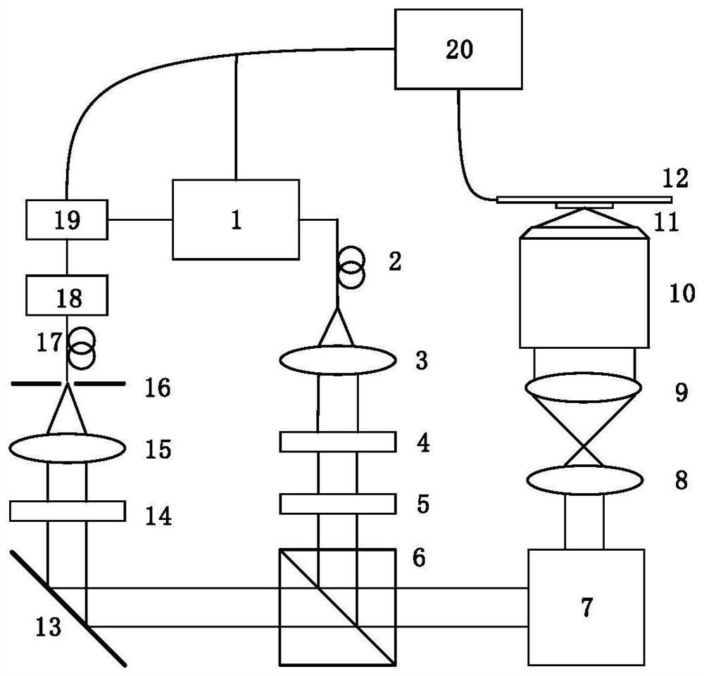
[0075] Such as figure 2 Shown is a schematic diagram of a time-domain lifetime measurement imaging system based on a spectral detection module, including: 488nm laser 1, single-mode polarization-maintaining fiber 2, collimator lens 3, 1 / 2 wave plate 4, 1 / 4 wave plate 5. Dichromatic mirror 6, galvanometer scanning system 7, scanning mirror 8, field mirror 9, high numerical aperture objective lens 10, sample stage 12, mirror 13, narrow-band filter 14, converging lens 15, pinhole 16, multimode Optical fiber 17 , spectroscopic module 18 , detector array 19 , time-correlated single photon counter (TCSPC) 20 and control system 21 .

[0076] Among them, the 1 / 2 wave plate 4 and the 1 / 4 wave plate 5 can adjust the polarization state of the excitation light to circularly polarized light, thereby improving the excitation efficiency of the sample; the scanning mirror 8 and the field lens 9 form a 4f system, so that the incident excitation The size of the beam of light matches the numer...

Embodiment 2

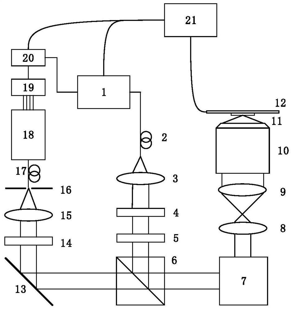
[0085] Such as Figure 6 It is a schematic diagram of a time-domain lifetime measurement imaging system device based on the spectral detection parallel counting module, including: 488nm laser 1, single-mode polarization-maintaining fiber 2, collimator lens 3, 1 / 2 wave plate 4, 1 / 4 wave plate 5. Dichromatic mirror 6, galvanometer scanning system 7, scanning mirror 8, field mirror 9, high numerical aperture objective lens 10, sample stage 12, mirror 13, narrow-band filter 14, converging lens 15, pinhole 16, multimode Optical fiber 17 , spectroscopic module 18 , detector array 19 , time-correlated single photon counter array (TCSPC array) 20 and control system 21 .

[0086] Among them, the 1 / 2 wave plate 4 and the 1 / 4 wave plate 5 can adjust the polarization state of the excitation light to circularly polarized light, thereby improving the excitation efficiency of the sample; the scanning mirror 8 and the field lens 9 form a 4f system, so that the incident excitation The size of...

Embodiment 3

[0094] Such as Figure 7 Shown is a schematic diagram of a time-domain lifetime measurement imaging system based on a spectral detection module and a parallel detection module, including: 488nm laser 1, single-mode polarization-maintaining fiber 2, collimator lens 3, 1 / 2 wave plate 4, 1 / 4 wave plate 5, dichroic mirror 6, galvanometer scanning system 7, scanning mirror 8, field mirror 9, high numerical aperture objective lens 10, sample stage 12, mirror 13, narrow-band filter 14, converging lens 15, multimode Fiber bundle 17 , spectroscopic module 18 , detector array 19 , time-correlated single photon counter (TCSPC) array 20 and control system 21 .

[0095] Among them, the 1 / 2 wave plate 4 and the 1 / 4 wave plate 5 can adjust the polarization state of the excitation light to circularly polarized light, thereby improving the excitation efficiency of the sample; the scanning mirror 8 and the field lens 9 form a 4f system, so that the incident excitation The size of the beam of ...


PUM


Abstract

The invention discloses a fluorescence lifetime imaging device based on a spectrum division technology. The fluorescence lifetime imaging device comprises a light source and a microscope objective forconverging exciting light emitted by the light source and exciting a sample to emit fluorescence, and the device is provided with a spectrum division module used for carrying out spectrum division onfluorescence collected by the microscope objective, a detection module used for receiving fluorescent molecules of different wave bands after spectrum division, and a counting module used for carrying out photon counting on the fluorescent molecules and calculating fluorescence lifetime information. Meanwhile, the invention further discloses a fluorescence lifetime imaging method based on the spectrum division technology. According to the invention, a spectrum division technology is introduced, and wide-band fluorescence signals are decomposed to different channels through the spectrum division module and are received by different detectors, so that the influence of dead time of a single detector on fluorescence lifetime measurement in a traditional method is greatly relieved, and the problem of photon accumulation effect of fluorescence lifetime measurement is relieved; and the effective detection efficiency of photons is improved, and the life imaging speed is increased.

Description

technical field [0001] The invention belongs to the field of fluorescence lifetime imaging, in particular to a method and device for fluorescence lifetime imaging based on spectral technology. Background technique [0002] In the field of biomedical imaging, super-resolution fluorescence imaging has always been the focus of biomedical research. Through special labeling of biomolecules, fluorescence optical microscopy plays an important role in observing subcellular structures. For fluorescence information, there are four basic physical dimensions, including intensity information, wavelength information (absorption spectrum and emission spectrum), lifetime information and polarization information. Due to the specificity of fluorescent labeling, high-contrast results of labeled structures can be obtained only by acquiring intensity information, so most current imaging techniques are aimed at intensity information. In addition to intensity information, wavelength information i...

Claims


Application Information

Patent Timeline
Patent Type & Authority Applications(China)
IPC IPC(8): G01N21/64G01J3/44G01J3/28G01J3/12G01J3/02G02B21/00
CPCG01J3/0205G01J3/12G01J3/2803G01J3/2823G01J3/4406G01N21/6408G01N21/6458G01N2021/6417G02B21/0076
Inventor 匡翠方刘少聪董婉潔王文生
Owner ZHEJIANG UNIV
Why Eureka
Try Eureka