Leakage circuit breaker

A leakage circuit breaker and circuit breaker technology, which is applied to circuit breakers with leakage function, short circuit, and overload fields, and can solve problems such as no leakage circuit breaker is found

Pending Publication Date: 2018-06-05
温州奥来电器有限公司
View PDF0 Cites 3 Cited by
  • Summary
  • Abstract
  • Description
  • Claims
  • Application Information

AI Technical Summary

Problems solved by technology

[0002] There is no earth leakage circuit breaker close to the structure of this patent

Method used


Image

  • Leakage circuit breaker
  • Leakage circuit breaker
  • Leakage circuit breaker

Examples


Embodiment Construction

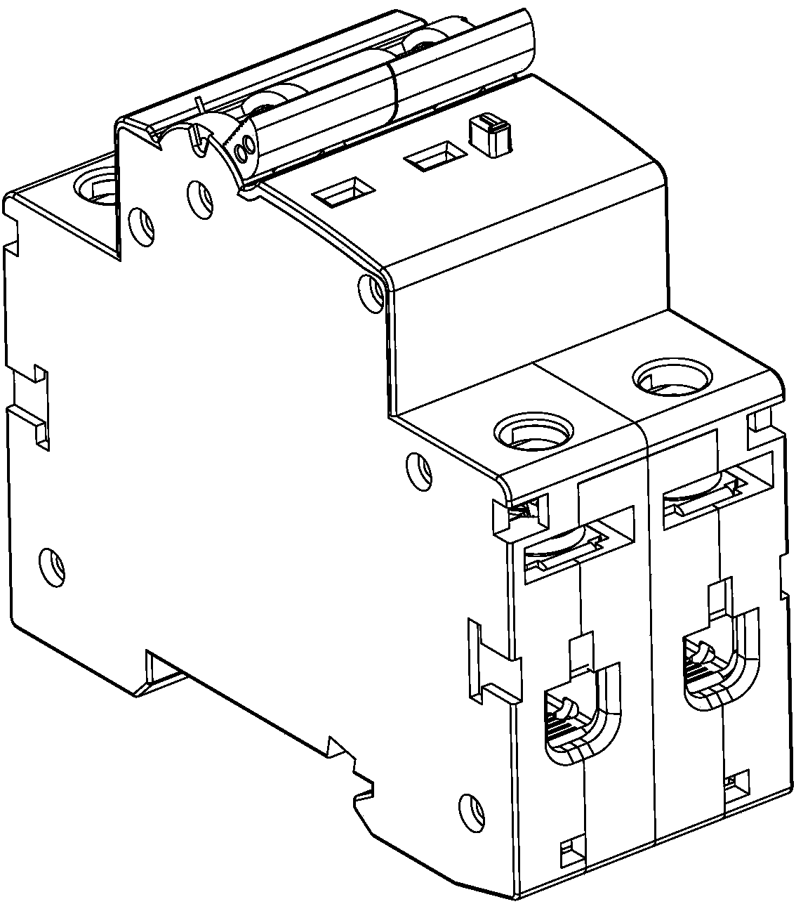
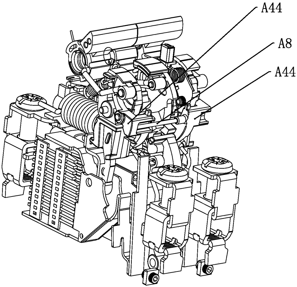
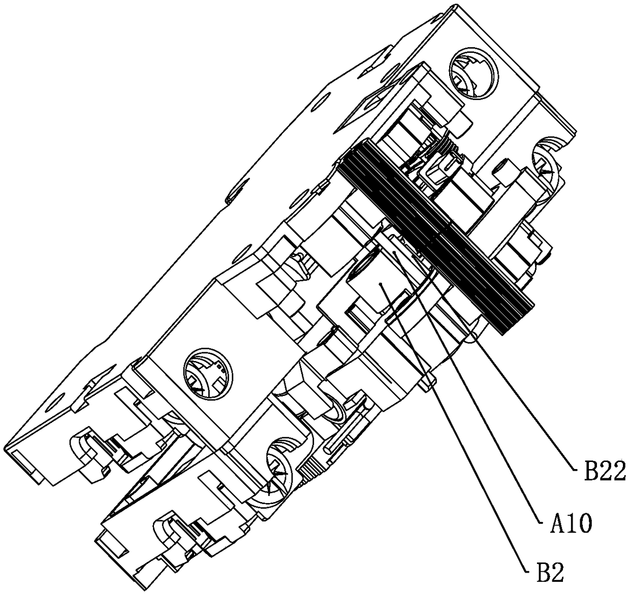
[0036] Such as Figure 1-22 As shown, a leakage circuit breaker includes a circuit breaker unit A and a leakage tripping unit B. The circuit breaker unit A is provided with the first and second groups, and the leakage tripping unit B is located between the two groups of circuit breaker units A , the base A1 of the first circuit breaker unit A and the base A1 of the second circuit breaker unit A are simultaneously used as the housing B1 of the leakage tripping unit B, the base A1 of the first circuit breaker unit A and the second circuit breaker unit A There is a long through hole A11 on the base A1, and the lock A44 in the first circuit breaker unit A and the lock A44 in the second circuit breaker unit A are set in linkage through the connecting rod A8, and the connecting rod A8 passes through the long through hole The hole A11 is set. In the embodiment of the present invention, a linkage rod A10 is set between the handle A9 of the handle operating device of the first circuit ...


PUM


Abstract

The invention relates to a circuit breaker, in particular to a circuit breaker with overload, short circuit and leakage functions. Through the adoption of the technical scheme, the leakage circuit breaker is characterized by comprising a first group of circuit breaker units, a second group of circuit breaker units and a leakage tripping unit, and the leakage tripping unit is positioned between thetwo groups of circuit breaker units. Through the adoption of the scheme, the circuit breaker overcomes the disadvantages in the prior art, and the novel leakage circuit breaker with reasonable structure and convenient installation is provided.

Description

technical field [0001] The invention relates to a circuit breaker, in particular to a circuit breaker with functions of overload, short circuit and leakage. Background technique [0002] Also do not find the earth leakage circuit breaker close to this patent structure at present. Contents of the invention [0003] The invention overcomes the shortcomings of the prior art and provides a novel leakage circuit breaker with reasonable structure and convenient installation. [0004] In order to achieve the above object, the technical solution adopted by the present invention is: a leakage circuit breaker, characterized in that it includes a circuit breaker unit and a leakage tripping unit, and the circuit breaker unit is provided with a first and a second group, and the leakage tripping The unit is located between two groups of circuit breaker units, the base of the first circuit breaker unit and the base of the second circuit breaker unit are also used as the housing of the l...

Claims


Application Information

Patent Timeline
Patent Type & Authority Applications(China)
IPC IPC(8): H01H71/10H01H83/04
CPCH01H71/1009H01H83/04
Inventor 周维峰林凯胡广召
Owner 温州奥来电器有限公司
Why Eureka
Try Eureka