Welding device of pipe fittings

A pipe fitting welding and pipeline technology, which is applied in the direction of auxiliary devices, welding equipment, auxiliary welding equipment, etc., can solve the problems of difficult installation and fixation of pipe fittings, low work efficiency, time-consuming and labor-intensive problems, and achieve improved welding quality and welding efficiency, and reliable positioning Effect

Inactive Publication Date: 2018-06-08
ANHUI XINRUI HEAVY IND
9 Cites 0 Cited by

AI-Extracted Technical Summary

Problems solved by technology

[0002] Pipe fittings are widely used in various fields of industrial production. In practical applications, people often need to weld different pipe fittings together. At present, the welding of short pipe fittings has the following disadvantages: First, it is not easy to install and fix the pipe fittings before welding , us...

Method used

One end of two pipe fittings 11 to be welded is placed in pipeline installation groove 8, and the other end is supported in the support groove on support plate 12 and realizes seamless docking under the effect of clip spring 9, two pipe fittings 11 The positioning is firm; when wel...

Abstract

The invention discloses a welding device of pipe fittings. Supporting platforms are arranged at the two sides of the upper end face of a base of the device respectively, mounting grooves are formed inthe supporting platforms and are internally provided with turntables, the turntables are connected with one ends of rotary pin shafts, the other ends of the rotary pin shafts extend to the outer sides of the supporting platforms and are connected with stopping blocks, the turntables are internally provided with pipe mounting grooves, compressed springs are arranged on the bottom faces of the pipemounting grooves, a press sheet is arranged at one end of each compressed spring, two supporting plates are arranged between the supporting platforms, a rocking handle is arranged at one side of onesupporting platform and is connected to the stopping block, and the lower ends of the supporting plates are arranged in a mobile groove in the base of the device. One ends of two to-be-welded pipe fittings are placed in the pipe mounting grooves, the other ends of the to-be-welded pipe fittings are supported on the supporting plates and are in butt joint with each other under the effect of the compressed springs, in the welding process, people can use the rocking handle to rotate the pipe fittings, and thus whole-circle welding of connectors of the pipe fittings is facilitated.

Application Domain

Welding/cutting auxillary devicesAuxillary welding devices +2

Technology Topic

EngineeringButt joint +2

Image

  • Welding device of pipe fittings

Examples

  • Experimental program(1)

Example Embodiment

[0014] The following will clearly and completely describe the technical solutions in the embodiments of the present invention with reference to the accompanying drawings in the embodiments of the present invention. Obviously, the described embodiments are only part of the embodiments of the present invention, not all of them. Based on the embodiments of the present invention, all other embodiments obtained by persons of ordinary skill in the art without making creative efforts belong to the protection scope of the present invention.
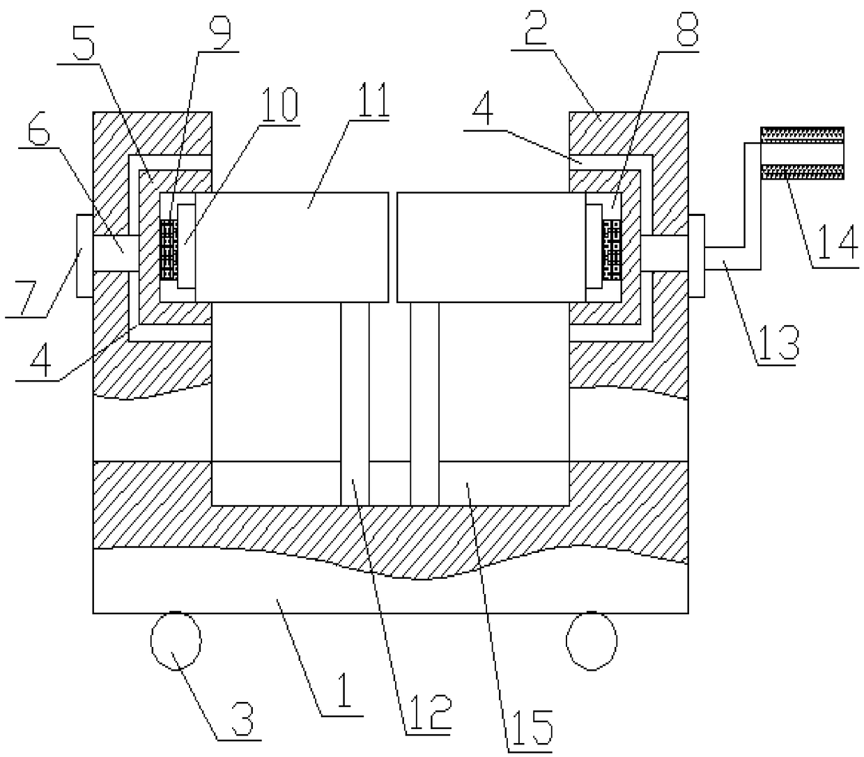
[0015] see figure 1 As shown, a pipe fitting welding device includes a device base 1, a support platform 2 is respectively provided on both sides of the upper end surface of the device base 1, and a roller 3 is provided on the lower end surface of the device base 1, and a mounting recess is arranged inside the support platform 2 Groove 4, the installation groove 4 is provided with a rotating disk 5, the rotating disk 5 is connected to one end of the rotating pin 6, the other end of the rotating pin 6 extends to the outside of the support table 2 and is connected to the stopper 7, the rotating disk 5 can rotate around the rotating pin shaft 6, the rotating disk 5 is provided with a pipeline installation groove 8, the bottom surface of the pipeline installation groove 8 is provided with a compression spring 9, and one end of the compression spring 9 A pressing piece 10 is provided, one end of the pipe fitting 11 to be welded compresses the compression spring 9 through the pressing piece 10, two supporting plates 12 are arranged between the two supporting platforms 2 and one side of the supporting platform 2 is provided with a rocker handle 13, the rocker handle 13 is provided with a protective cover 14 and is connected with the block 7, the lower end of the support plate 12 is arranged in the moving chute 15 on the device base 1, and its upper end surface is provided with a circular arc The supporting groove, the moving chute is a rectangular groove.
[0016] One end of the two pipe fittings 11 to be welded is placed in the pipe installation groove 8, and the other end is supported in the support groove on the support plate 12 and is seamlessly connected under the action of the compression spring 9, and the two pipe fittings 11 are firmly positioned; When welding the joint of two pipe fittings 11, people only need to use the crank handle 13 to realize the rotation of the pipe fittings, so as to facilitate full circle welding of the joint of two pipe fittings 11, greatly improving the welding quality and welding efficiency.
[0017] The above content is only an example and description of the structure of the present invention. Those skilled in the art make various modifications or supplements to the described specific embodiments or replace them in similar ways, as long as they do not deviate from the structure of the present invention. Or beyond the scope defined in the claims, all should belong to the protection scope of the present invention.

PUM

no PUM

Description & Claims & Application Information

We can also present the details of the Description, Claims and Application information to help users get a comprehensive understanding of the technical details of the patent, such as background art, summary of invention, brief description of drawings, description of embodiments, and other original content. On the other hand, users can also determine the specific scope of protection of the technology through the list of claims; as well as understand the changes in the life cycle of the technology with the presentation of the patent timeline. Login to view more.

Similar technology patents

Punch forming over-current ultraviolet sterilizer and manufacturing process for sterilization device of punch forming over-current ultraviolet sterilizer

ActiveCN105293622AImprove production efficiency and production qualityImprove welding quality and welding efficiency
Owner:TIANJIN MORUI ENVIRONMENTAL TECH

Polarizer stripping device for liquid crystal display panel

ActiveCN104808365AFirmly positionedlow peel strength
Owner:SUZHOU SAISHUOLA STAINLESS STEEL PROD CO LTD

Wheel sleeve part feeding device

PendingCN109335681ASimple structureFirmly positioned
Owner:YUHUAN CNC MACHINE TOOL

Robot-assisted continuous resistance welding equipment and welding method for thermoplastic materials

PendingCN111907069AImprove welding quality and welding efficiencyImprove welding efficiency
Owner:DALIAN UNIV OF TECH

Tie bar welding device

PendingCN111545961AGuaranteed force balanceImprove welding quality and welding efficiency
Owner:新疆福泰建设(集团)有限公司

Rotor milling cutter and blade fixing structure

PendingCN113245603AFirmly positionedNot easy to loose
Owner:四川天虎工具有限责任公司

Welding equipment and welding method for bottom frame of screw machine

PendingCN114161033Aaccurate locationImprove welding quality and welding efficiency
Owner:XINLEI COMPRESSOR CO LTD

Welding fixture with counting function

InactiveCN105290593Afast solderingImprove welding quality and welding efficiency
Owner:孙新梅

Classification and recommendation of technical efficacy words

  • Improve welding quality and welding efficiency
  • Firmly positioned

Positioning device between heat exchange tube and tube hole

ActiveCN103350311AEasy to operateImprove welding quality and welding efficiency
Owner:ZHANGHUAJI SUZHOU HEAVY EQUIP CO LTD

Automatic welding tool for straight splicing slits of base plates of dump trucks

InactiveCN102756193AImprove welding quality and welding efficiency
Owner:QINGTE GRP

Welding equipment and welding method for bottom frame of screw machine

PendingCN114161033Aaccurate locationImprove welding quality and welding efficiency
Owner:XINLEI COMPRESSOR CO LTD

Robot-assisted continuous resistance welding equipment and welding method for thermoplastic materials

PendingCN111907069AImprove welding quality and welding efficiencyImprove welding efficiency
Owner:DALIAN UNIV OF TECH

Welding fixture with counting function

InactiveCN105290593Afast solderingImprove welding quality and welding efficiency
Owner:孙新梅

Polarizer stripping device for liquid crystal display panel

ActiveCN104808365AFirmly positionedlow peel strength
Owner:SUZHOU SAISHUOLA STAINLESS STEEL PROD CO LTD

Wheel sleeve part feeding device

PendingCN109335681ASimple structureFirmly positioned
Owner:YUHUAN CNC MACHINE TOOL

Rotor milling cutter and blade fixing structure

PendingCN113245603AFirmly positionedNot easy to loose
Owner:四川天虎工具有限责任公司
Why Eureka
Try Eureka