

Rotor milling cutter and blade fixing structure
A fixed structure, rotor milling technology, used in milling cutters, milling machine equipment, manufacturing tools, etc., can solve the problems of loose displacement, unstable machining accuracy, and time difference between rotor machining accuracy, so as to achieve firm and reliable positioning and ensure machining. Accuracy and stability, not easy to loosen
- Summary
- Abstract
- Description
- Claims
- Application Information
AI Technical Summary
Problems solved by technology
Method used
Image


Examples
Embodiment Construction
[0036] The present invention will be further described below in conjunction with the accompanying drawings, but the protection scope of the present invention is not limited to the following description.
[0037] Such as Figure 1-10 Shown:
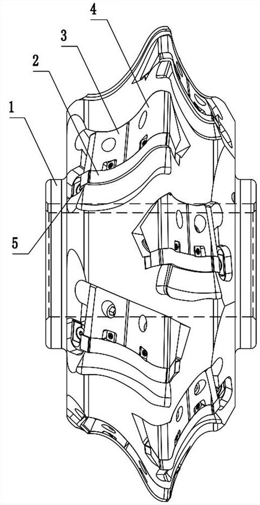
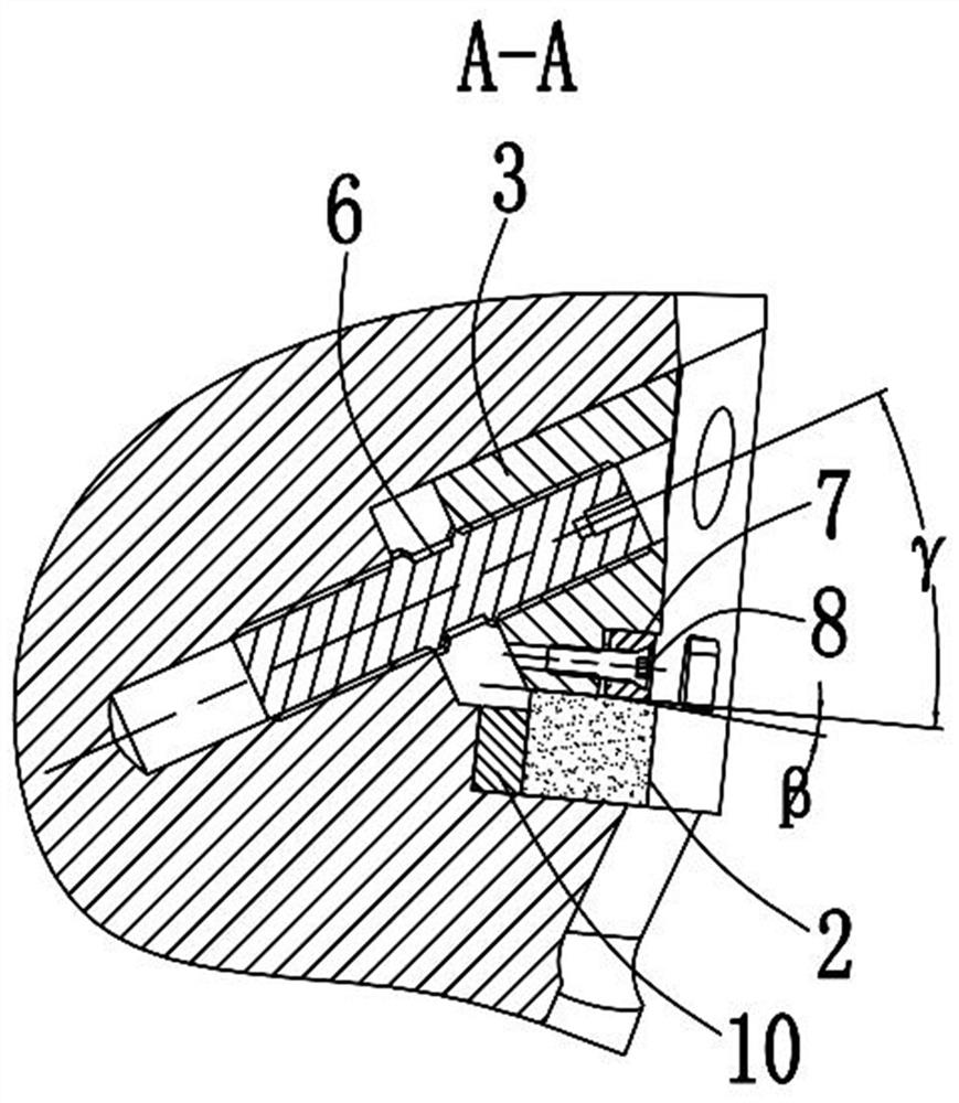
[0038] The invention provides a rotor milling cutter and a blade fixing structure, including a cutter body 1, a blade 2 and a pressing block; wherein:
[0039] The cutter body 1 is provided with a plurality of blade grooves,
[0040] Blocks 10 are installed on each of the blade slots,
[0041] Be provided with the briquetting groove 16 that is used for installing briquetting beside described blade groove,
[0042] The blade 2 is fixed on the spacer 10 through a pressing block to form a complete cutting edge 11 of the rotor milling cutter,
[0043] The blade positioning surface 22 of the blade 2 is provided with an adjusting block groove 13,
[0044] An adjusting block 5 for adjusting the angle of the blade 2 is installed on the adjust...
PUM
 Abstract
Description
Claims
Application Information