
Arraying device of pin sleeves

A technology for aligning devices and pin sleeves, which is applied in the field of aligning devices, and can solve problems such as the inability to guarantee the directionality of pin sleeves and affecting assembly

Inactive Publication Date: 2018-06-08
WUXI CHANGZHISHENG MACHINERY MFG CO LTD
View PDF1 Cites 0 Cited by
  • Summary
  • Abstract
  • Description
  • Claims
  • Application Information

AI Technical Summary

Problems solved by technology

[0003] In view of the above problems, the present invention provides a device for aligning pin sleeves, which can solve the technical problem that the directionality of the pin sleeves cannot be guaranteed and affects assembly during the transportation process.

Method used


Image

  • Arraying device of pin sleeves
  • Arraying device of pin sleeves
  • Arraying device of pin sleeves

Examples


Embodiment Construction

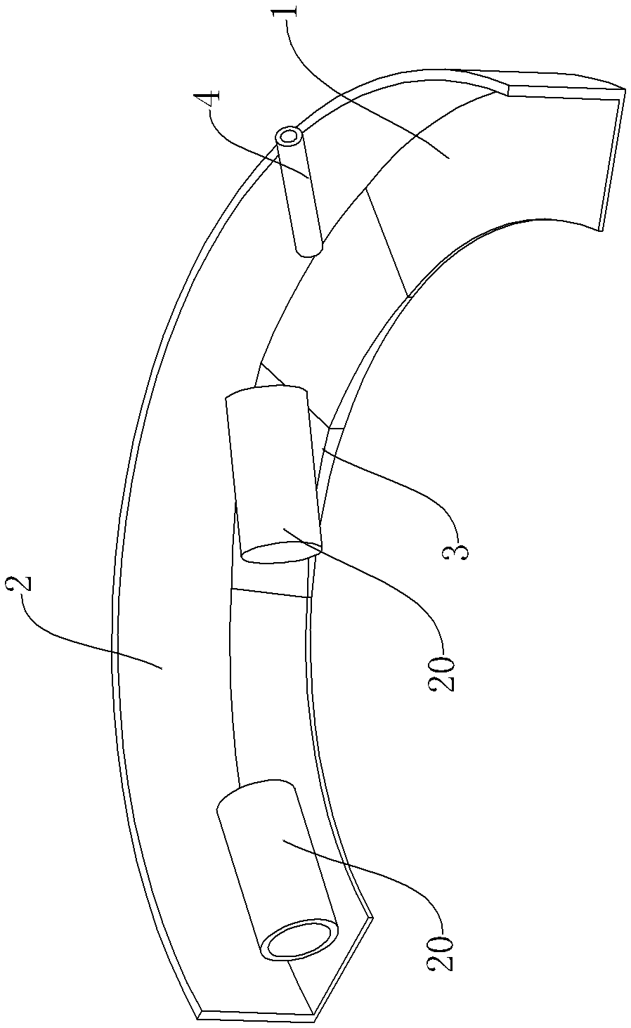
[0012] Such as figure 1 As shown, an alignment device of pin sleeves, the pin sleeve is a hollow structure and one end is encapsulated by the bottom plate, the alignment device includes a slide plate 1, a guide plate 2, a nozzle 4, an air source and a drive unit, the slide plate 1 is arranged horizontally, and the side of the slide plate 1 The arc-shaped guide plate 2 is fixed on the upper part, and the slope plate 3 forming an up and down slope structure is arranged in the middle part. The nozzle 4 is fixed on the top of the slide plate 1 and set towards the downhill direction of the slope plate 3. The nozzle 4 is connected to the air source through a pipeline, and the drive unit It is used to provide the initial velocity of the pin sleeve.

[0013] When the pin sleeve is about to go downhill, the air resistance received by the end of the package through the bottom plate and the end of the opening are different. When the end of the opening faces the nozzle, the air resistance...


PUM


Abstract

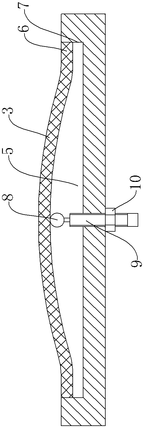
The invention provides an arraying device of pin sleeves. The problems that the direction of the pin sleeves can not be ensured and assembling is influenced in the conveying process are solved. The pin sleeves are of a hollow structure, and one end of each pin sleeve is packaged through a bottom plate. The arraying device of the pin sleeves is characterized by comprising a slide plate, a guide plate, a nozzle, an air source and a driving unit, the slide plate is horizontally arranged, the arc-shaped guide plate is fixed to one side of the slide plate, a slope plate of an up-down slope structure is arranged in the middle of the slide plate. The nozzle is fixed above the slide plate and is in the down slope direction of the slope plate. The nozzle is connected with the air source through a pipeline. The driving unit is used for providing the initial speed of the pin sleeves. The slide plate is fixed to the base and provided with a slide plate groove. The slope plate is a rubber plate. The two ends of the rubber plate are combined with the two side walls of the slide plate groove through vulcanization. The middle of the rubber plate is supported above the slide plate groove through afirst supporting mechanism.

Description

technical field [0001] The invention relates to the field of alignment devices, in particular to an alignment device for pin sleeves. Background technique [0002] A kind of pin sleeve, its structure is as figure 1 As shown, the pin sleeve is a hollow structure and one end is encapsulated through the bottom plate. In the assembly process of the assembly line, after the pin sleeve is clamped by the manipulator, its open end is inserted downward into the positioning hole of the part and matched with the pin. Although the assembly line is equipped with a pin sleeve conveying mechanism, which can also realize the one-by-one delivery of the pin sleeves, it cannot ensure the directionality of the pin sleeves, which affects the assembly of the pin sleeves. Contents of the invention [0003] In view of the above problems, the present invention provides a device for arranging the pin sleeves, which can solve the technical problem that the directionality of the pin sleeves cannot ...

Claims


Application Information

Patent Timeline
Patent Type & Authority Applications(China)
IPC IPC(8): B23P19/00
CPCB23P19/002
Inventor 吴坚
Owner WUXI CHANGZHISHENG MACHINERY MFG CO LTD
Learn More