
Horizontal-type particle high-speed implanting device

A technology for implanting devices and granules, which is applied in the field of planting materials for granules, can solve problems such as failure to meet the precision requirements of granules, abnormal quality of granules, etc., and achieve the effect of avoiding rebound and ensuring quality

Pending Publication Date: 2018-06-08
武汉大坦智能装备科技有限公司
View PDF0 Cites 3 Cited by
  • Summary
  • Abstract
  • Description
  • Claims
  • Application Information

AI Technical Summary

Problems solved by technology

[0003] However, for finer particles such as granular pills and explosive beads used in cigarettes, on the one hand, the long-term vibration of the vibrating feeding tray may cause abnormal quality of the particles; Accuracy requirements for materials and sub-materials

Method used


Image

  • Horizontal-type particle high-speed implanting device
  • Horizontal-type particle high-speed implanting device
  • Horizontal-type particle high-speed implanting device

Examples


Embodiment Construction

[0030] In order to describe the technical content, structural features, achieved goals and effects of the present invention in detail, the following will be described in detail in conjunction with the embodiments and accompanying drawings.

[0031] Such as Figure 1-Figure 6 As shown, the horizontal particle high-speed implantation device provided by the present invention has a storage bin 200 for accommodating the particle P and a plant material port 431a, and the horizontal particle high-speed implantation device includes a fixed seat 300, which can be opposite to the fixed seat 300 rotations of the rotating seat 400, the first pushing mechanism 600, and the second pushing mechanism 700; the surrounding side of the rotating seat 400 is sequentially provided with a number of internal feeding channels 421 connected to the storage bin 200 and external feeding ports connected to the plant material port 431a Road 431, and there is a height difference between the inner feeding cha...

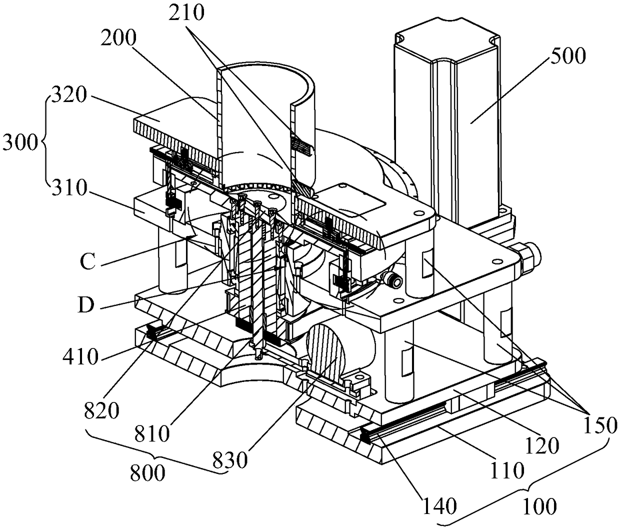
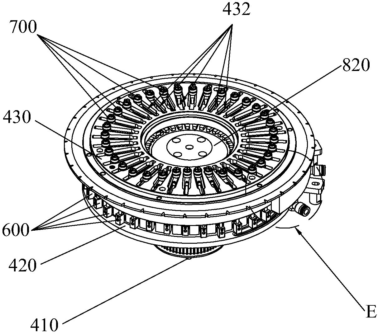
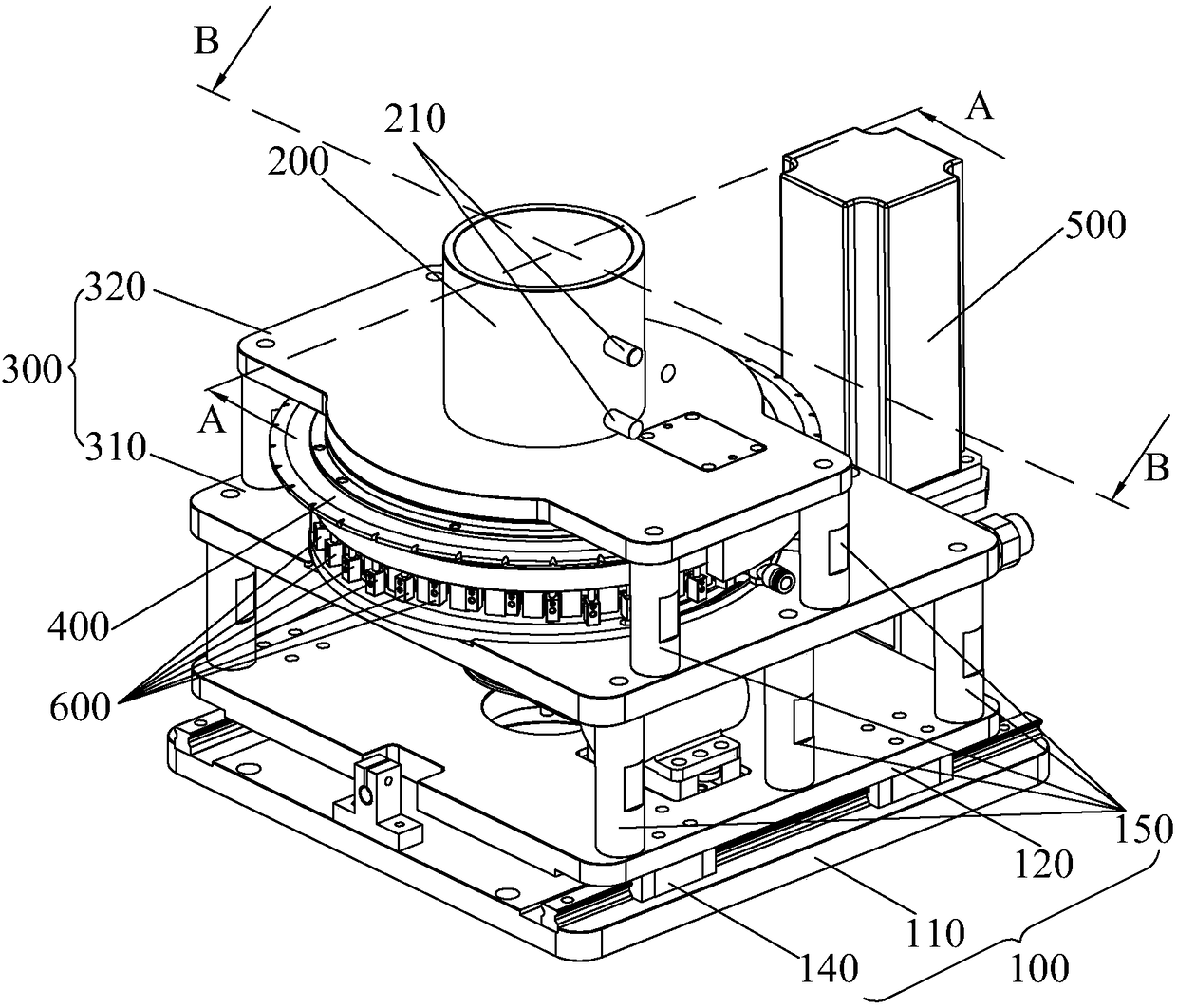

PUM


Abstract

A horizontal-type particle high-speed implanting device provided by the invention comprises a material storing cabin, a material implanting opening, a fixed seat, a rotatable seat capable of rotatingrelative to the fixed seat, a first pushing mechanism, a second pushing mechanism and an air collecting mechanism. A plurality of inner material feeding channels communicating with the material storing cabin and a plurality of outer material feeding channels communicating with the material implanting opening are sequentially formed in the circumferential side of the rotatable seat, and the heightdifference exists between the inner material feeding channels and the outer material feeding channels in the vertical direction. The first pushing mechanism is used for pushing particles in the innermaterial feeding channels to the outer material feeding channels, and the second pushing mechanism is used for pushing the particles in the outer material feeding channels to the outer side of the material implanting opening. The fixed seat comprises a first cam driving plate and a second cam driving plate, and the first cam driving plate and the second cam driving plate are arranged on the upperside and the lower side of the rotatable seat correspondingly to drive the first pushing mechanism and the second pushing mechanism correspondingly. The gas collecting mechanism is used for positioning the particles, the material storing cabin is fixedly arranged in the fixed seat, and a flow guiding block is fixedly arranged on the lower side of the inner wall of the cylindrical material storingcabin.

Description

technical field [0001] The invention relates to a production feeding device, in particular to a plant material mechanism for granular matter. Background technique [0002] For the particles that need to be separated and installed into the product one by one, during the production process, the particle feeding mechanism can be used to separate the particles one by one and then feed them one by one. A common particle feeding mechanism is a vibrating feeding tray, which places the particles in a stepped feeding trough through vibration and feeds them sequentially. The vibrating feeding tray can adapt to most occasions that do not require high quality. [0003] However, for finer particles such as granular pills and explosive beads used in cigarettes, on the one hand, the long-term vibration of the vibrating feeding tray may cause abnormal quality of the particles; Accuracy requirements for materials and sub-materials. [0004] For this reason, there is an urgent need for a g...

Claims


Application Information

Patent Timeline
Patent Type & Authority Applications(China)
IPC IPC(8): B65G29/00
CPCB65G29/00
Inventor 曹淮胡跃兵杜智育
Owner 武汉大坦智能装备科技有限公司
Learn More