Slidable rail lower plate for automatic transmission of continuously welded rails

A technology of seamless lines and under-rail pads, applied in the directions of roads, tracks, fixed rails, etc., can solve the problems affecting the stability of high-speed trains such as track structure safety, track bottom voids, and line irregularities. The effect of reducing the beam-rail interaction of the seamless line, reducing the maintenance and repair workload, and avoiding the expansion of the track

Pending Publication Date: 2018-06-08
EAST CHINA JIAOTONG UNIVERSITY
View PDF0 Cites 0 Cited by
  • Summary
  • Abstract
  • Description
  • Claims
  • Application Information

AI Technical Summary

Problems solved by technology

These two measures have a good effect on reducing the beam-rail interaction and releasing the internal stress of the rail, but both will increase the relative displacement of the beam-rail at the end of the beam; , so that the rail will drive the rubber pad under the rail to move together, and the longitudinal friction of the rubber pad will decrease when it is reset, and the rubber pad cannot be completely reset with the rail, which will cause part of the rubber pad to slide out. If things go on like this, the sliding length of the rubber pad will become more and more The longer it is; when the rubber pad under the rail slides out, its support elasticity decreases, and even the bottom of the rail is empty, resulting in uneven lines, which seriously affect the stability of the high-speed train running and the safety of the track structure
Therefore, the existing methods and measures can no longer meet the requirements of high-speed railways, and it is urgent to develop a special under-rail backing plate, which can not only reduce the longitudinal resistance of the fasteners without reducing the buckle pressure, but also ensure The backing plate under the rail will not slide out when the normal sliding between the rail and the fastener

Method used


Image

  • Slidable rail lower plate for automatic transmission of continuously welded rails
  • Slidable rail lower plate for automatic transmission of continuously welded rails
  • Slidable rail lower plate for automatic transmission of continuously welded rails

Examples


Embodiment Construction

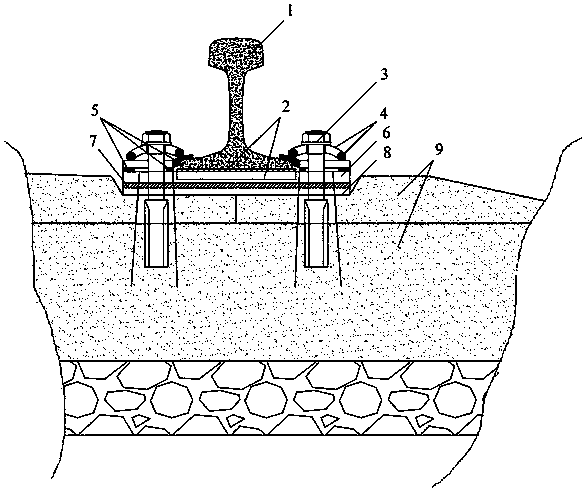
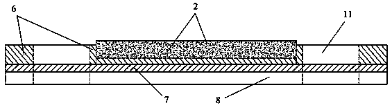
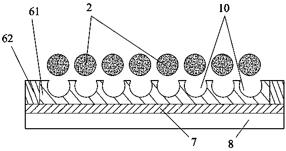
[0014] A slidable backing plate under the rail that can realize the automatic stress relief of the seamless line, including a sliding backing plate 6, a rubber backing plate 7 and a height-adjusting backing plate 8 arranged in sequence from top to bottom, and the three-layer backing plate passes through Fastener bolts 3, fastener elastic strips 4, and fastener gaskets 5 are installed on the concrete sleeper 9, and it is characterized in that the sliding backing plate 6 is composed of an inner sliding backing plate 61 and an outer sliding backing plate 62 , the inner sliding backing plate 61 is embedded in the outer sliding backing plate 62, the inner sliding backing plate 61 can be taken out from the outer sliding backing plate 62, and the inner sliding backing plate 61 is provided with Several transparent roller grooves 10 are arranged in parallel between the roller grooves 10. The radial section of the roller grooves 10 is an arc, and its diameter is the same as that of the r...


PUM


Abstract

The invention relates to a slidable rail lower plate for automatic transmission of continuously welded rails. The slidable rail lower plate for automatic transmission of continuously welded rails includes a sliding pad, a rubber pad and a height adjusting pad. The slidable rail lower plate for automatic transmission of continuously welded rails is characterized in that the sliding pad is composedof an inner sliding pad and an outer slidding pad. The inner sliding pad is embedded in the outer sliding pad. A plurality of transparent roller grooves are formed in the direction perpendicular to the longitudinal direction of the inner sliding pad and the rail. The radial cross section of the roller groove is an arc, the diameter of the arc is the same as the arc of the roller, and the roller isinserted into the roller groove. Compared with the existing stress relief measures, the slidable rail lower plate for automatic transmission of continuously welded rails can realize the reduction ofthe longitudinal resistance without reducing the pressure of the fastener, and can also ensure that the rail pad does not slip out with the normal sliding between the rail and the fastener, and realizes the automation of the stress relief of the rails of the seamless track, greatly reduces the maintenance and repair workload, effectively compensates for the deficiencies of the existing measures, and avoids the problems such as expansion track and rail break caused by excessive internal stress of the rail.

Description

technical field [0001] The invention relates to a slidable backing plate under a rail which can realize the automatic relaxation of seamless line stress. Background technique [0002] With the rapid development of high-speed railway, in order to meet the safety and stability of operation and the comfort of passengers, high-speed railway puts forward higher requirements for track structure and offline foundation. The seamless line on the bridge has many advantages. Advantages are widely used in high-speed railway construction. The stress on the seamless line on the bridge is much more complicated than that on the roadbed. In addition to the temperature load, train dynamic load, and braking load, it is also affected by the additional force caused by bridge expansion and deflection deformation, which makes the inside of the rail Huge stresses, while fasteners are subjected to huge tensile forces. If the interaction force between beams and rails is too large, it will cause pro...

Claims


Application Information

Patent Timeline
Patent Type & Authority Applications(China)
IPC IPC(8): E01B9/68
CPCE01B9/68
Inventor 张鹏飞桂昊连西妮雷晓燕冯青松李明华
Owner EAST CHINA JIAOTONG UNIVERSITY
Why Eureka
Try Eureka