Convection dehumidification time-lapse machine

A technology of timer and AC contactor, which is applied in heating methods, lighting and heating equipment, heating and ventilation control systems, etc., can solve problems such as poor dehumidification effect, and achieve good dehumidification effect.

Inactive Publication Date: 2018-06-08
QINGDAO TECHNOLOGICAL UNIVERSITY
View PDF6 Cites 1 Cited by
  • Summary
  • Abstract
  • Description
  • Claims
  • Application Information

AI Technical Summary

Problems solved by technology

[0005] The purpose of the present invention is to provide a convective dehumidification timer, which solves the problem of poor dehumidification effect of natural ventilation in the underground garage

Method used


Image

  • Convection dehumidification time-lapse machine
  • Convection dehumidification time-lapse machine
  • Convection dehumidification time-lapse machine

Examples


Embodiment Construction

[0023] The present invention will be described in detail below in combination with specific embodiments.

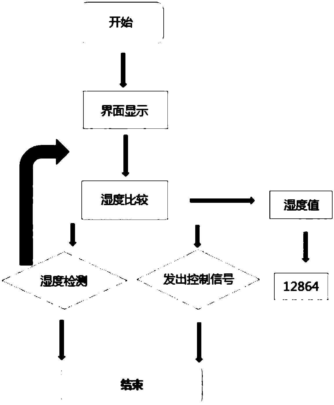
[0024] The whole system of the convection dehumidification timer of the present invention is composed of five parts: a control unit, a display unit, a detection unit, a driving amplification unit and an execution unit.

[0025] In the control unit part, the STM32 single-chip microcomputer is used as the main control chip, and the humidity signal (humidity) output by the detection unit is compared with two humidity thresholds (humidity_set1 and humidity_set2, and humidity_set1>humidity_set2), so as to send a control signal through the driving amplifier circuit.

[0026] The display unit uses a 12864 chip to display the humidity of the environment in real time.

[0027] The detection unit adopts DHT11 digital temperature and humidity sensor.

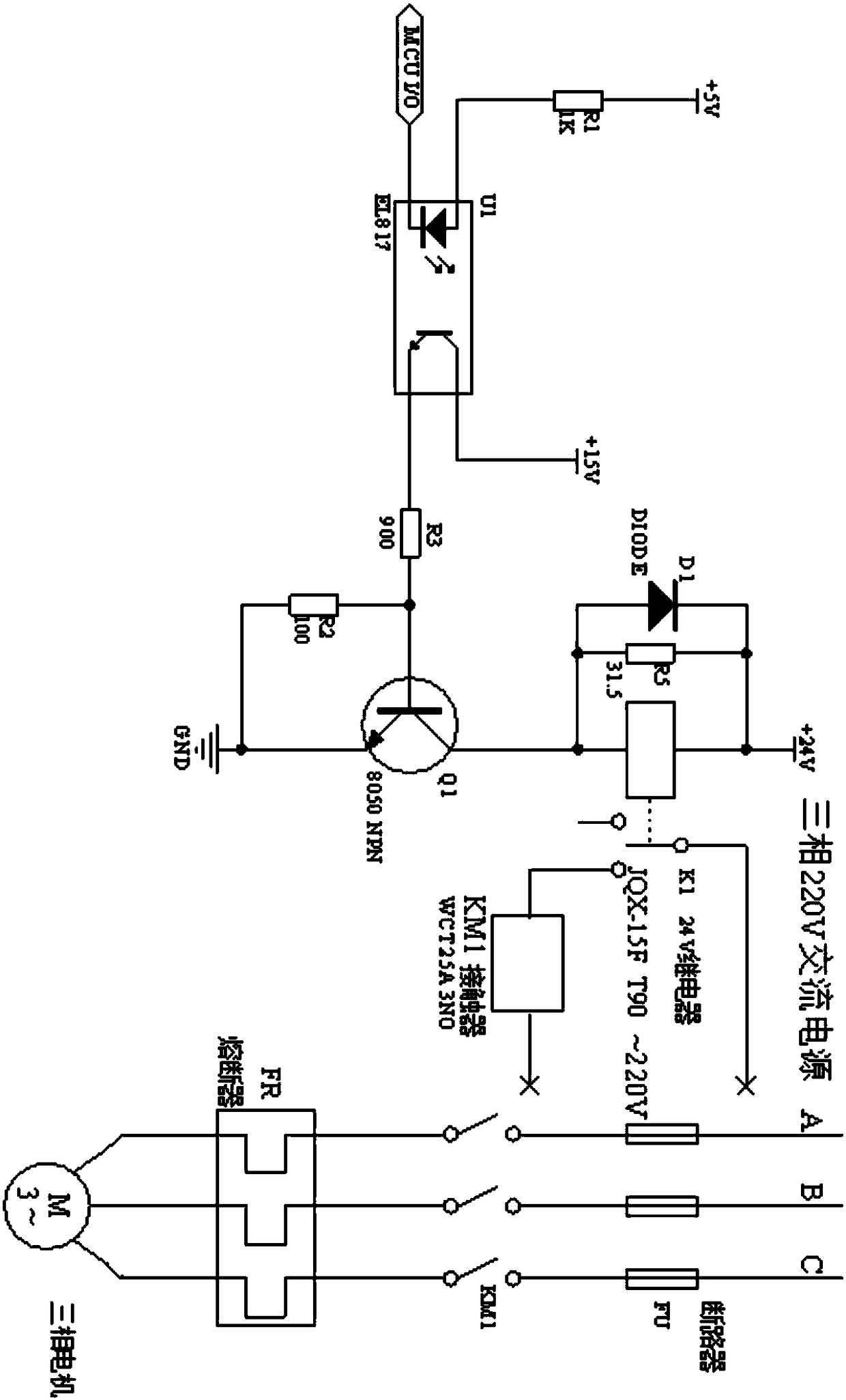
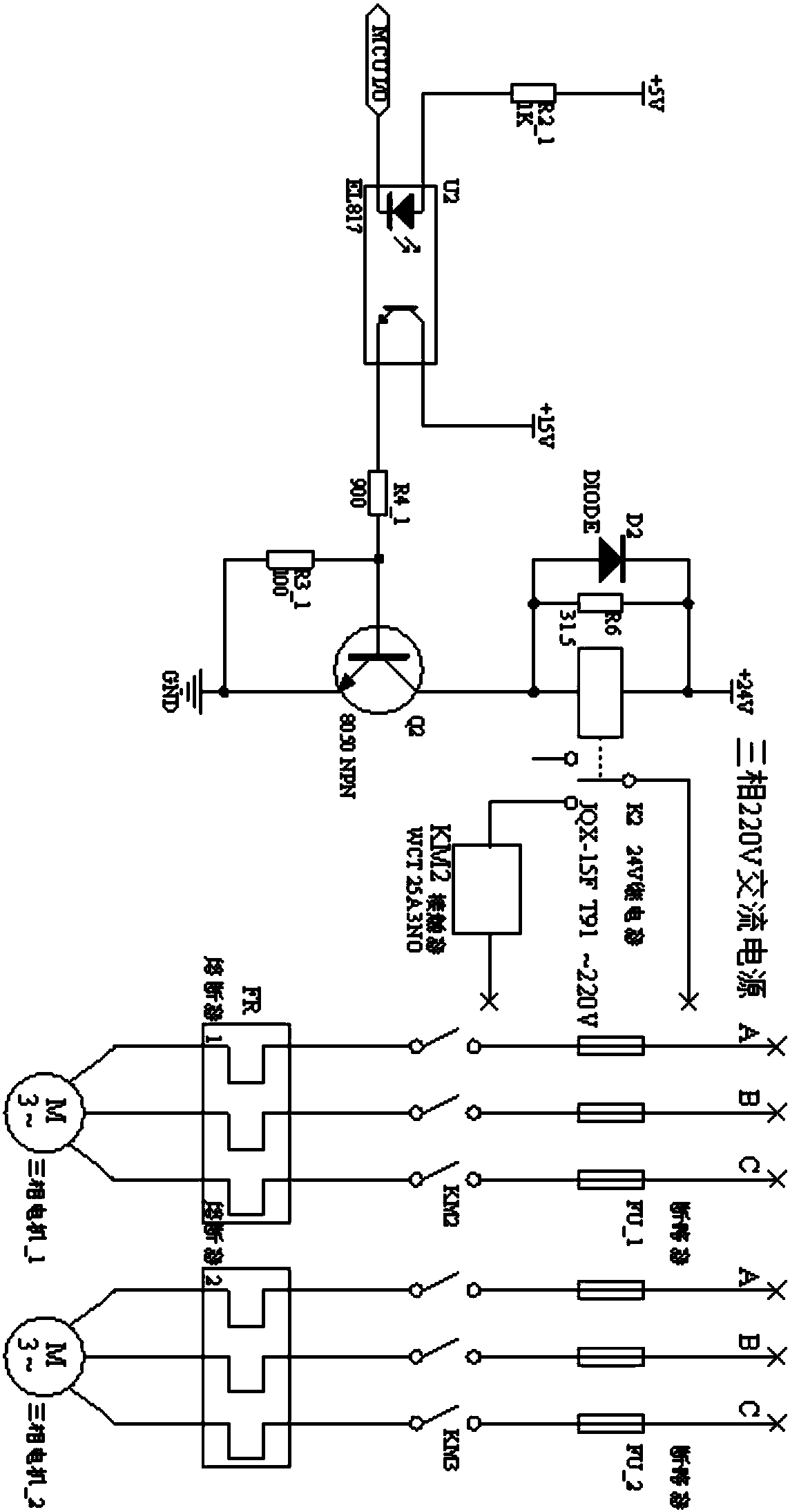
[0028] The drive amplifier unit is composed of optocoupler and NPN transistor. This unit is a bridge connecting the control unit an...


PUM


Abstract

The invention discloses a convection dehumidification time-lapse machine.According to the convection dehumidification time-lapse machine, a control unit compares a humidity signal outputby a detectingunit with two given humidity thresholds, thereby sending a control signal through a driving amplifying circuit; a display unit displays the humidity of the environment in real time;the detecting unitadopts a digital temperature and humidity sensor; the driving amplifying unit is composed of an optocoupler and an NPN transistor to realize the effect that a small signal controls a large signal, and a small signal generated by a singlechip is amplified and transmitted to an execution unit; the execution unit is composed of a 24V relay, a 220V AC contactor, a circuit breaker, a fuse and a draught fan, the relay is used in the DC circuit, the normally open contact of the relay controls the energization and de-energization of the AC contactor coil, and the normally open contact of the AC contactor controls the starting and stopping of the draught fan. The convection dehumidification time-lapse machine has the advantages that the underground garage can be automatically dehumidified, and thedehumidification effect is good.

Description

technical field [0001] The invention belongs to the technical field of electronic devices and relates to a convective dehumidification timer. Background technique [0002] The existing hotel dehumidification system is not ideal for improving underground garages. In the summer months of each year, it often rains in coastal cities, so the humidity in these cities is higher than that in ordinary cities. The indoor and outdoor humidity is much higher than that of inland cities. The environment of underground garages is generally relatively closed, so good ventilation cannot be carried out. Water vapor molecules will liquefy when encountering cold surfaces, and then flow along the surfaces to In the surrounding space, the humidity value of the environment will increase sharply. Excessive humidity will bring many disadvantages to the environment. The increase in the humidity of the environment will accelerate the corrosion of iron objects, reduce the durability of the objects, and...

Claims


Application Information

Patent Timeline
Patent Type & Authority Applications(China)
IPC IPC(8): F24F3/14F24F11/89F24F11/00F24F110/20
CPCF24F3/14
Inventor 赵景波王代超沈汉文廖鹏浩段杰姜岩
Owner QINGDAO TECHNOLOGICAL UNIVERSITY
Why Eureka
Try Eureka