Cable bridge convenient for drainage and moisture-proof treatment
A technology for cable tray and moisture-proof treatment, applied in electrical components and other directions, can solve the problems of shortening the service life of cable trays and cables, water accumulation on the tray, affecting the service life of cables, etc. replacement effect
- Summary
- Abstract
- Description
- Claims
- Application Information
AI Technical Summary
Problems solved by technology
Method used
Image
Examples
Embodiment 1
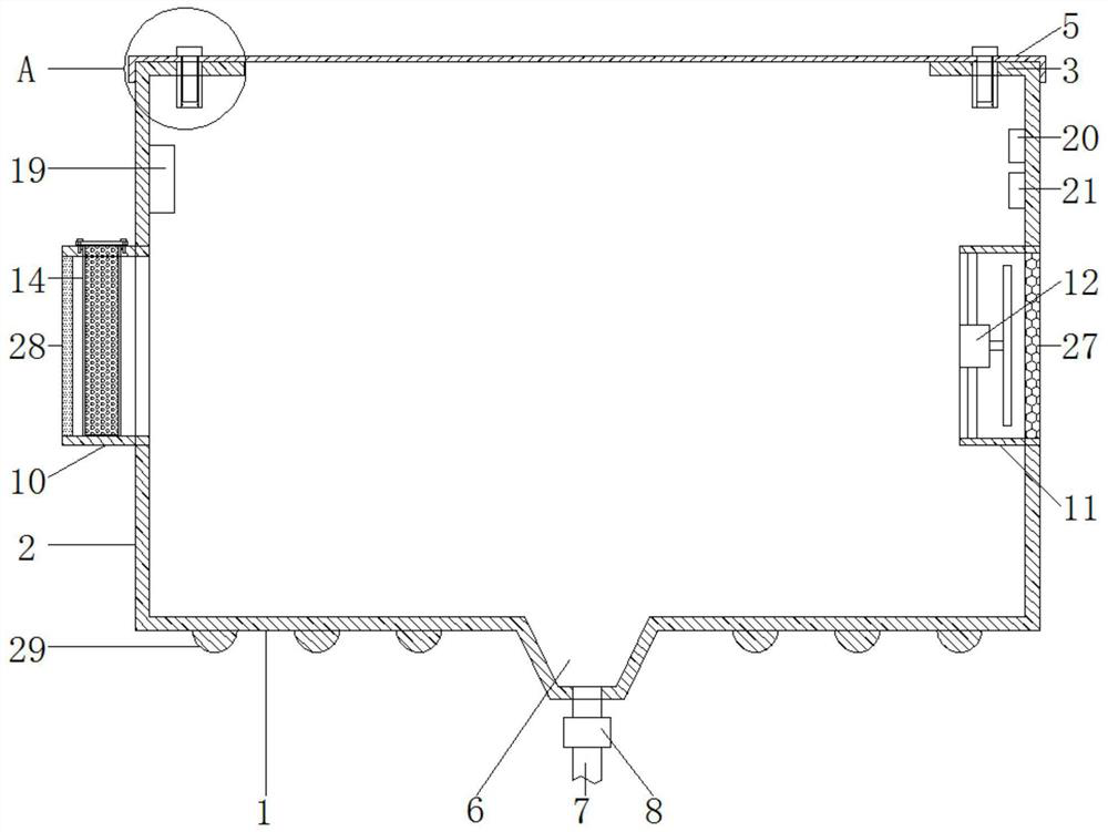
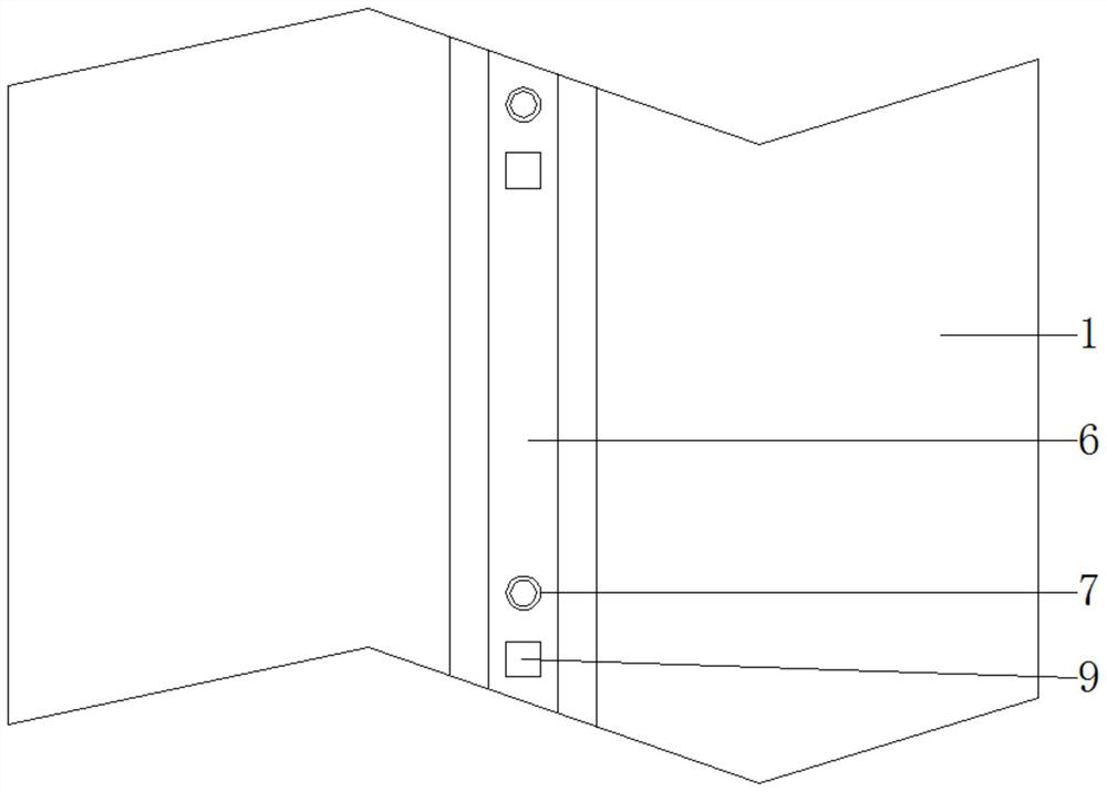
[0032] see Figure 1-8 , according to an embodiment of the present invention, a cable bridge that is convenient for drainage and moisture-proof treatment includes a bottom plate 1, side plates 2 are fixed on both sides of the bottom plate 1, and the upper ends of the side plates 2 are fixed with inward The curling 3 is fixed with a cover plate 5 by the first bolt 4, and the middle part of the bottom plate 1 is processed with a sump 6, and the sump 6 is fixedly embedded with a plurality of drainage pipes 7 at equal intervals. And the middle part of the drain pipe 7 is equipped with a solenoid valve 8, a number of water immersion sensors 9 are fixed on the sump 6, and an air intake box 10 is fixedly embedded in the side plate 2 on one side, far away from the inlet. The side plate 2 on one side of the gas box 10 is fixedly embedded with an exhaust tube 11, and an exhaust fan 12 is fixedly installed in the exhaust tube 11 through a connecting rod, and a rectangular opening 13 is p...
Embodiment 2
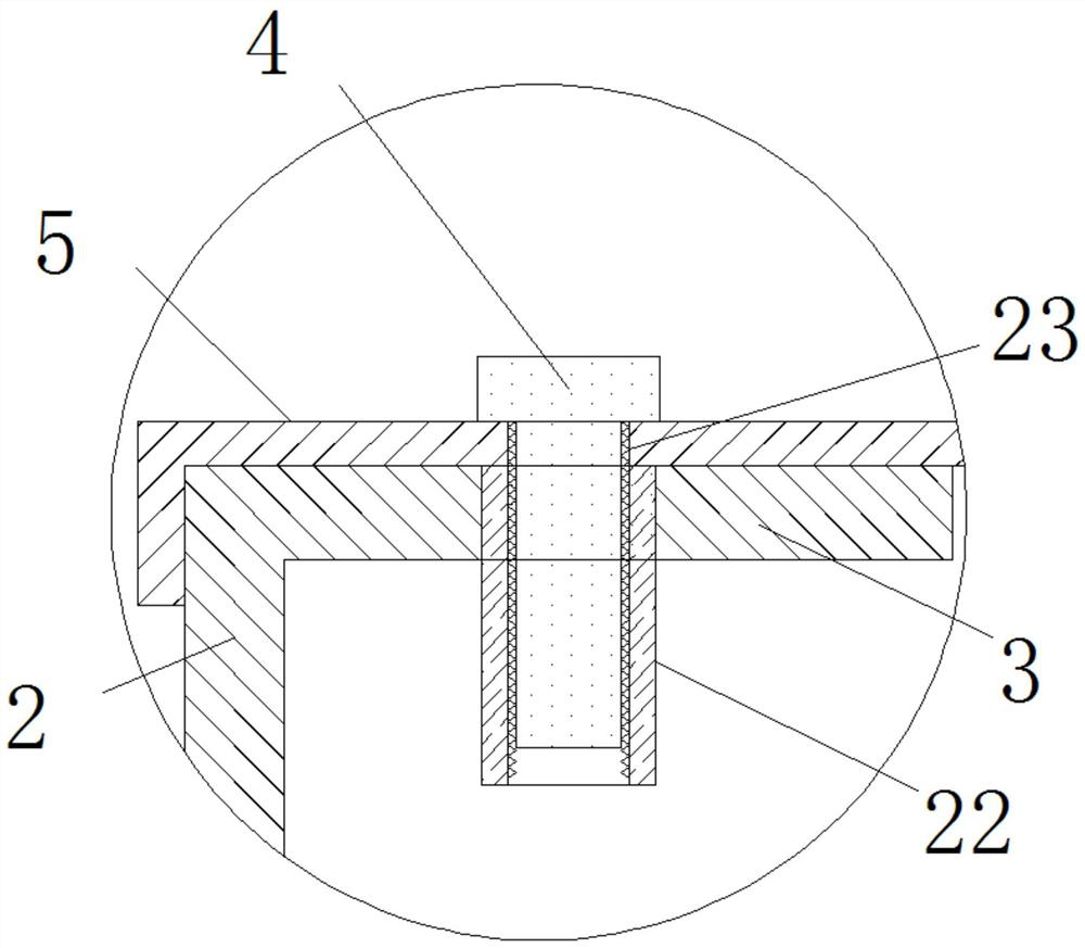
[0035] see figure 2 , 4 , 5, 6, 7 and 8, for the crimping 3, the crimping 3 is fixedly embedded with a number of threaded cylinders 22, and both sides of the cover plate 5 are provided with a number of threads that match the threaded cylinders 22 the first through hole 23, the first bolt 4 passes through the first through hole 23 and is threadedly connected with the threaded barrel 22; for the sealing plate 18, the four corners of the sealing plate 18 are provided with second through holes 24, four of the rectangular frame 16 are provided with a third perforation 25 that matches the second perforation 24, and the upper end of the air box 10 is provided with a number of four that match the third perforation 25. Matching threaded holes 26, and the threaded holes 26 are respectively arranged at the four corners close to the rectangular opening 13; for the exhaust tube 11, the outer end of the exhaust tube 11 is fixed with a protective net 27.
[0036] Through the above scheme...
Embodiment 3
[0038] see figure 1 and 4 , for the air intake box 10, the outer end of the air intake box 10 is fixed with a waterproof breathable film 28; for the bottom plate 1, a number of reinforcing ribs 29 are fixed under the bottom plate 1; for the bottom plate 1, Regarding the side plate 2 and the beading 3, the bottom plate 1, the side plate 2 and the beading 3 are integrally formed, and the water collection tank 6 is made by cold pressing.
[0039] Through the above solution of the present invention, the waterproof and breathable membrane 28 can prevent external rainwater from entering the air intake box 10, and the reinforcing ribs 29 can increase the mechanical strength of the bottom plate 1, so that the bottom plate 1 is not easily deformed or damaged.
[0040] In order to facilitate the understanding of the above-mentioned technical solution of the present invention, the working principle or operation mode of the present invention in the actual process will be described in det...
PUM
 Abstract
Description
Claims
Application Information
 - R&D
- Intellectual Property
- Life Sciences
- Materials
- Tech Scout
- Unparalleled Data Quality
- Higher Quality Content
- 60% Fewer Hallucinations
Browse by: Latest US Patents, China's latest patents, Technical Efficacy Thesaurus, Application Domain, Technology Topic, Popular Technical Reports.
© 2025 PatSnap. All rights reserved.Legal|Privacy policy|Modern Slavery Act Transparency Statement|Sitemap|About US| Contact US: help@patsnap.com


