
Chip mounter

A placement machine and placement head technology, applied in the direction of electrical components, electrical components, etc., can solve the problems of high cost of manipulators, low efficiency of LED lamp bead placement, and production speed that cannot meet the demand, so as to improve placement efficiency and production The effect of speed satisfaction and labor intensity reduction

Pending Publication Date: 2018-06-08
SHENZHEN ETON AUTOMATION EQUIP
View PDF7 Cites 7 Cited by
  • Summary
  • Abstract
  • Description
  • Claims
  • Application Information

AI Technical Summary

Problems solved by technology

In the prior art, the LED lamp bead is generally transferred to the PCB board by a robot. This method leads to low efficiency of LED lamp bead placement, and the production speed cannot meet the demand. At the same time, the cost of the robot is expensive.

Method used


Image

  • Chip mounter
  • Chip mounter
  • Chip mounter

Examples


Embodiment Construction

[0043] The present invention will be further described below in conjunction with the accompanying drawings and embodiments.

[0044] The idea, specific structure and technical effects of the present invention will be clearly and completely described below in conjunction with the embodiments and accompanying drawings, so as to fully understand the purpose, features and effects of the present invention. Apparently, the described embodiments are only some of the embodiments of the present invention, rather than all of them. Based on the embodiments of the present invention, other embodiments obtained by those skilled in the art without creative efforts belong to The protection scope of the present invention. In addition, all the connection / connection relationships involved in the patent do not simply refer to the direct connection of components, but mean that a better connection structure can be formed by adding or reducing connection accessories according to specific implementat...


PUM


Abstract

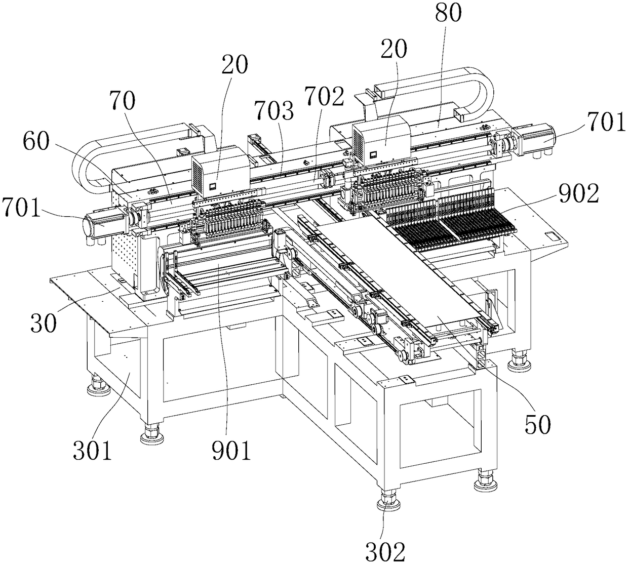
The present invention discloses a chip mounter, and relates to the technical field of chip mounters. The chip mounter comprises a working platform, an X-shaft cross beam, a first X-shaft device, a second X-shaft device, a transportation platform and chip mounting head devices. The X-shaft cross beam is located above the working platform, the first X-shaft device and the second X-shaft device are symmetrically installed on the X-shaft cross beam, and the chip mounting head devices are respectively slidingly installed on the first X-shaft device and the second X-shaft device; the transportationplatform is arranged on the working platform, the working platform is located below the X-shaft cross beam, and the transportation platform is configured to drive a carrying tool to move in a Y-shaftdirection; one side of the first X-shaft device is provided with a first feeder; and one side of the second X-shaft device is provided with a second feeder. The two chip mounting head devices are employed to perform chip mounting operation of a PCB in order so as to improve the chip mounting efficiency of a LED lamp bead and meet the demand of a production speed.

Description

technical field [0001] The present invention relates to the technical field of placement machines, more specifically, the present invention relates to a placement machine. Background technique [0002] LED light strings are widely used in the decoration of architectural shapes, bridges, arches, corridors, stairs, billboards, etc., and can also be used in car decoration and interior decoration. The structure of the existing light string generally includes two wires and a plurality of LED lamp beads, wherein the LED lamp beads are respectively connected to the two wires. [0003] During production and manufacturing, it is necessary to weld the LED lamp bead and the pad of the PCB board to achieve electrical conduction. This process is referred to as the patch of the LED lamp bead. In the prior art, the LED lamp bead is generally transferred to the PCB board by a manipulator. This method leads to low efficiency of LED lamp bead placement, the production speed cannot meet the d...

Claims


Application Information

Patent Timeline
Patent Type & Authority Applications(China)
IPC IPC(8): H05K13/04
CPCH05K13/0408
Inventor 余耀国杨建军
Owner SHENZHEN ETON AUTOMATION EQUIP
Learn More