Telescopic shoes dryer

A shoe dryer and telescopic technology, applied in the field of shoe drying devices, can solve the problem that the shoe dryer cannot dry shoes of different sizes, and achieve the effects of avoiding rapid aging, increasing current, and improving efficiency

Inactive Publication Date: 2018-06-12
宁波隆锐机械制造有限公司
View PDF5 Cites 6 Cited by
  • Summary
  • Abstract
  • Description
  • Claims
  • Application Information

AI Technical Summary

Problems solved by technology

[0003] This solution intends to provide a telescopic shoe dryer to solve the p

Method used


Image

  • Telescopic shoes dryer
  • Telescopic shoes dryer

Examples


Embodiment Construction

[0014] Further detailed explanation through specific implementation mode below:

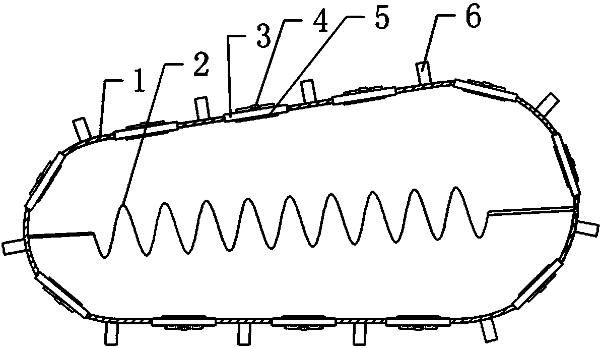
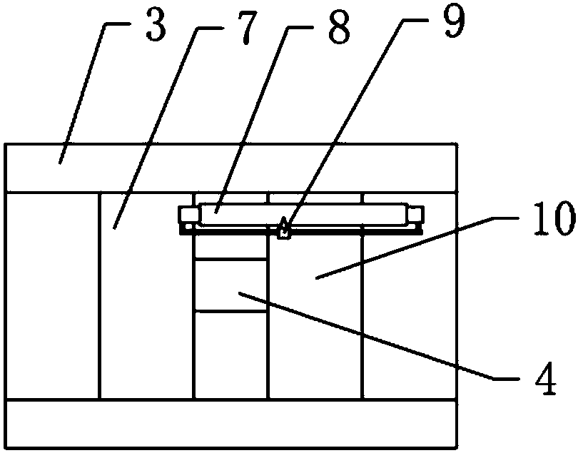
[0015] The reference signs in the accompanying drawings of the description include: elastic airbag 1, heating element 2, heat sink 3, water-absorbing expansion block 4, heat conduction block 5, protruding rod 6, first slider 7, resistance coil 8, sliding sheet 9, The second slider 10.

[0016] The embodiment is basically as attached figure 1 and figure 2 Shown: telescopic shoe dryer, including elastic airbag 1, inside elastic airbag 1 is equipped with heating element 2, heating element 2 is a resistance heating wire arranged in the shape of a helical spring, and connecting rods are fixed at both ends of heating element 2 , the connecting rod is preferably made of glass fiber. The end of the connecting rod far away from the heating element 2 is bonded to the elastic airbag 1, so that the heating element 2 is arranged laterally in the elastic airbag 1, and the length of the heating element 2 ca...


PUM


Abstract

The invention relates to the technical field of shoes drying devices, in particular to a telescopic shoes dryer. The shoes dryer comprises a heating element, and further comprises an elastic airbag, wherein the heating element is located inside the elastic airbag, the outer surface of the elastic airbag is provided with a plurality of protruding rods, a plurality of aluminum heat sinks are embedded in the elastic airbag, the heat sinks are provided with through holes, one end, close to the elastic airbag, of each through hole is sealedly and fixedly connected with a copper heat conducting block, each through hole is slidably covered with a first sliding block and second sliding block made of aluminum, each first sliding block and the corresponding second sliding block are both slidably connected to the heat sink, a water absorption expansion block is connected between each first sliding block and the corresponding second sliding block, a slide rheostat is connected between each first sliding block and the corresponding second sliding block, the slide rheostat is connected in series with the heating element, and as the distance between each first sliding block and the correspondingsecond sliding block increases, the resistance value of the resistor in series with the heating element on the slide rheostat decreases. The problem that the shoes dryer in the prior art cannot dry shoes of different sizes is solved.

Description

technical field [0001] The solution relates to the technical field of shoe drying devices, specifically a retractable shoe dryer. Background technique [0002] A shoe dryer is a small appliance specially designed for drying shoes. Existing shoe dryers generally include two cooling fins with heating elements. After the heating elements are energized, the heating elements generate heat and transfer the heat to the cooling fins. The cooling fins transfer the heat to the air in the shoes, thereby making the shoes The temperature inside the shoe rises to evaporate the water inside the shoe, thereby realizing the drying operation of the shoe. The size of the heat sink of the existing shoe dryer is fixed. When preparing to dry smaller shoes, the embarrassing situation often occurs because the heat sink is too large to be placed in the shoe; When the shoes are drying, because the heat sink is too small, the gap between the heat sink and the inner wall of the shoe is relatively lar...

Claims


Application Information

Patent Timeline
IPC IPC(8): A47L23/20
CPCA47L23/205
Inventor 孙文清
Owner 宁波隆锐机械制造有限公司
Why Eureka
Try Eureka