
Die assembly used for light sheet machining and using method thereof

A compression molding device and steel plate technology, applied in the field of compression molding devices and compression molding devices for thin steel plate processing, can solve the problems of inconvenient removal of model cards, affecting the accuracy of compression molding, and the position of steel plates cannot be firmly fixed, etc., to achieve convenient removal, High molding efficiency and firm fixation

Inactive Publication Date: 2018-06-12
丁年生
View PDF1 Cites 1 Cited by
  • Summary
  • Abstract
  • Description
  • Claims
  • Application Information

AI Technical Summary

Problems solved by technology

[0003] But existing device that is used for steel plate pressing die still has certain defect when using, although existing device that is used for steel plate pressing die can press steel plate, the position of steel plate can not be firmly fixed in the pressing die process, in pressing When the mold is molded, the offset will affect the accuracy of the mold, and the existing device for the steel plate mold, the pressed model is stuck in the steel plate after the mold is completed, and it is inconvenient to take out

Method used


Image

  • Die assembly used for light sheet machining and using method thereof
  • Die assembly used for light sheet machining and using method thereof
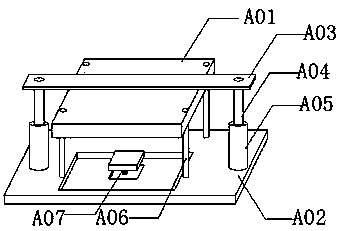
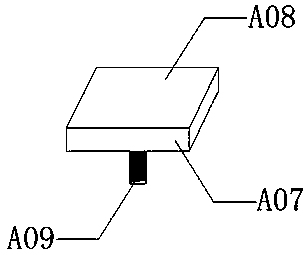
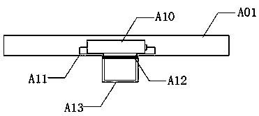
  • Die assembly used for light sheet machining and using method thereof

Examples


Embodiment Construction

[0022] The following will clearly and completely describe the technical solutions in the embodiments of the present invention with reference to the accompanying drawings in the embodiments of the present invention. Obviously, the described embodiments are only some, not all, embodiments of the present invention. Based on the embodiments of the present invention, all other embodiments obtained by persons of ordinary skill in the art without making creative efforts belong to the protection scope of the present invention.

[0023] see Figure 1-4 As shown, a die device for thin steel plate processing and its use method include a die plate A01 and a clamp plate A02, a drive plate A03 is welded above the press plate A01, and a hydraulic rod A04 is welded to both ends of the drive plate A03. The lower end of the hydraulic rod A04 is engaged with the hydraulic tank A05, several guide rods A06 are welded on the top of the clamp A02, the middle part of the clamp A02 is provided with a ...


PUM


Abstract

The invention discloses a die assembly used for light sheet machining and a using method thereof. The die assembly comprises a die plate, a clamping plate, a transmission plate, a hydraulic rod, a hydraulic box, a guide rod, a supporting device, a supporting plate, a spring support, an electricity box, a guide line, a first electromagnet, a die, a fixing groove, a clamping groove and a second electromagnet. The die assembly has the beneficial effects that by arranging the spring support and the first electromagnet at the bottom of the supporting device, the first electromagnet is energized toadsorb steel sheets, the spring support is compressed by the steel sheets to be clamped in the fixing groove and fixed, after die pressing is completed, the first electromagnet is powered off, the steel sheets are pushed by the spring support to return to the original position, thus, the steel sheets can be fixed and taken out conveniently, and the die pressing efficiency is improved. By arrangingthe second electromagnet in the die, after the die completes die pressing operation after making contact with the steel sheets, the second electromagnet is energized and thus can adsorb models pressed from the steel sheets, and the models can be taken out conveniently. The die assembly has the characteristics of being high in die pressing efficiency, simple and convenient to use.

Description

technical field [0001] The invention relates to a die device, in particular to a die device for processing thin steel plates and a method for using the same, belonging to the application field of steel plate processing. Background technique [0002] The steel plate is a flat-shaped steel material that is poured with molten steel and pressed after cooling. The steel plate is flat-shaped and rectangular, and can be directly rolled or cut from a wide steel strip. Sheets are classified by steel type, including ordinary steel, high-quality steel, alloy steel, spring steel, stainless steel, tool steel, heat-resistant steel, bearing steel, silicon steel, and industrial pure iron sheets, etc.; by professional use, there are plates for oil drums, Enamel plates, bulletproof plates, etc.; according to the surface coating, there are galvanized sheets, tinned sheets, lead-plated sheets, plastic composite steel sheets, etc. [0003] But existing device that is used for steel plate pressi...

Claims


Application Information

Patent Timeline
IPC IPC(8): B21D28/02B21D43/00B21D45/02B21D28/14
CPCB21D28/02B21D28/14B21D43/003B21D45/02
Inventor 丁年生
Owner 丁年生
Learn More