
Multifunctional electronic barrier gate with intercepting function

A multi-functional, electronic technology, applied in the direction of roads, roads, buildings, etc., can solve problems such as increasing the load of barriers, consumption of crossbars, and accelerated aging of barriers, so as to reduce the probability of failure, stabilize the mechanism structure, and improve security. performance effect

Inactive Publication Date: 2018-06-12
JINJIANG SULONG ELECTRONICS TECH CO LTD
View PDF0 Cites 2 Cited by
  • Summary
  • Abstract
  • Description
  • Claims
  • Application Information

AI Technical Summary

Problems solved by technology

[0003] Considering the safety factor, the speed of the crossbar of the general barrier gate is relatively slow during the process of lowering the crossbar, which will take a while to lower the crossbar. During this time, if the distance between the two vehicles is relatively close and the speed is fast, There is a possibility that two vehicles will drive through the gate at the same time, which reduces the security effect of the gate. Not only that, but nowadays, most residential areas only allow small cars to enter, and large vehicles need to be authenticated before they can enter. In this case, If barrier gates and height limits are installed at the same time, it will not only increase the cost, but also prevent large vehicles from entering the community. If only barrier gates are installed, the barrier gates will need to be opened frequently when small cars pass by, increasing the load on the motors of the barrier gates and accelerating Aging of barrier gates

Method used


Image

  • Multifunctional electronic barrier gate with intercepting function
  • Multifunctional electronic barrier gate with intercepting function
  • Multifunctional electronic barrier gate with intercepting function

Examples


Embodiment Construction

[0024] The present invention will now be described in further detail with reference to the drawings. These drawings are all simplified schematic diagrams, which merely illustrate the basic structure of the present invention in a schematic manner, so they only show the structures related to the present invention.

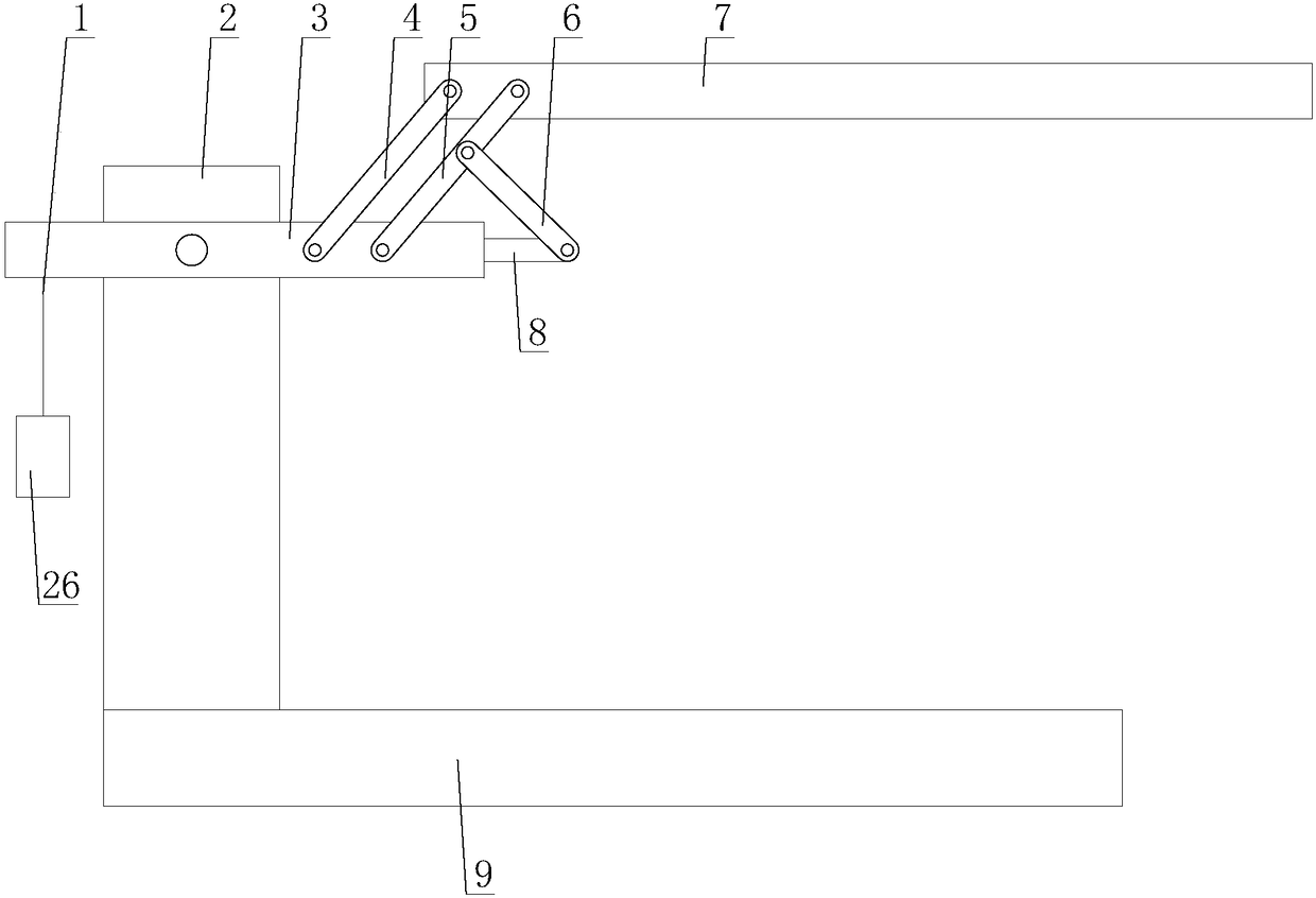
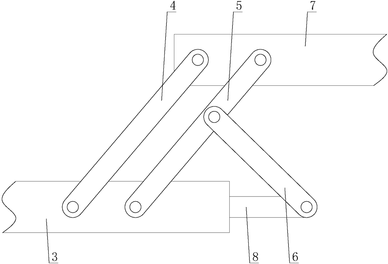
[0025] Such as figure 1 As shown, a multifunctional electronic barrier with interception function includes a main body 2, a first crossbar 3, and a second crossbar 7, and also includes a switching mechanism and an interception mechanism. The interception mechanism is arranged below the main body 2. The first crossbar 3 is hinged to the main body 2, and the first crossbar 3 is connected to the second crossbar 7 through a switching mechanism;

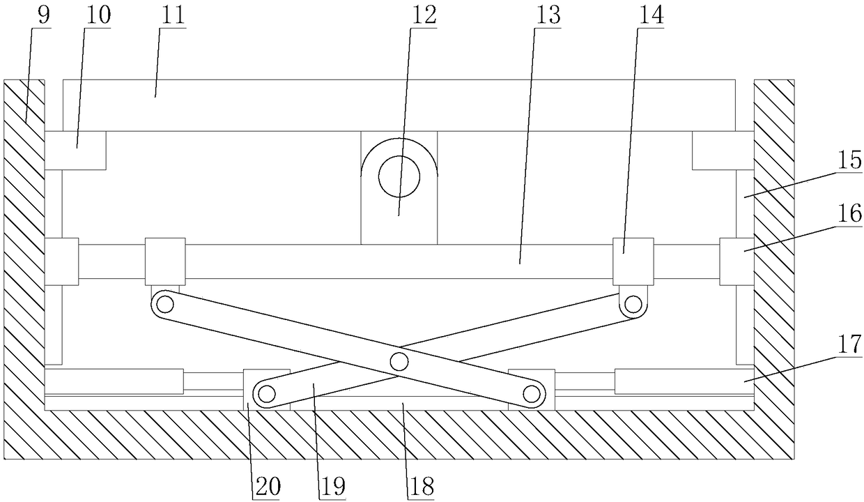
[0026] Such as figure 2 As shown, the interception mechanism includes a base 9, a top plate 11, a support rod 12, a lifting rod 13, a transmission assembly, a second guide rail 18, two support blocks 10, two lifting blocks 16, two f...


PUM


Abstract

The invention relates to a multifunctional electronic barrier gate with an intercepting function. The multifunctional electronic barrier gate comprises a body, a first cross rod, a second cross rod, aswitching mechanism and an intercepting mechanism. The intercepting mechanism comprises a base, a top plate, a supporting rod, a lifting rod, a transmission component, a second guide rail, two supporting blocks, two lifting blocks, two first driving components and two first guide rails, the switching mechanism comprises a second driving component, a telescopic rod, a first transmission rod, a first connecting rod and a second connecting rod, the first driving component comprises a cylinder and a sliding block, and the transmission component comprises two second transmission rods and two sleeves. According to the multifunctional electronic barrier gate with the intercepting function, when a front vehicle passes the barrier gate, the probability that a rear vehicle passes the barrier gate along with the front vehicle is reduced by the intercepting mechanism, so that security and protection performances of the barrier gate are improved, the barrier gate has a vehicle stopping function and further has a height limiting function, and practicability of the barrier gate is improved.

Description

Technical field [0001] The invention relates to the field of security equipment, in particular to a multifunctional electronic barrier with interception function. Background technique [0002] The barrier, also known as the car stopper, is a channel entrance and exit management equipment specially used for restricting motor vehicles on the road. It is now widely used in road toll stations and parking lot systems to manage vehicle channels. It is used to manage vehicle access. The electric barrier can be independent The landing rod can be realized through wireless remote control, and the automatic management state can also be implemented through the parking lot management system. The card will be released when entering the venue, and the parking fee will be automatically released when the parking fee is charged. [0003] Taking into account safety factors, the speed of the crossbar of the general barrier is relatively slow during the process of lowering, which leads to a period of t...

Claims


Application Information

Patent Timeline
IPC IPC(8): E01F13/04
CPCE01F13/04
Inventor 张亚萍
Owner JINJIANG SULONG ELECTRONICS TECH CO LTD
Learn More