Transformer substation intelligent identification system

An intelligent identification and substation technology, applied in the field of intelligent identification, can solve the problems of increasing the workload of the staff, wasting manpower and material resources, etc., and achieve the effect of simple structure, high security performance and effective identification

Pending Publication Date: 2021-04-23
ZIYANG POWER SUPPLY COMPANY STATE GRID SICHUAN ELECTRIC POWER
9 Cites 0 Cited by

AI-Extracted Technical Summary

Problems solved by technology

Substations generally refer to step-down substations with a voltage level below 110kV; substations include "step-up and step-down" substations of various voltage levels, so the care of substations is very import...

Abstract

The invention discloses a transformer substation intelligent identification system which comprises a shell and a processor, and is characterized in that one side of the shell is provided with a display screen, a camera device is arranged above the display screen, a card reading device is arranged in the middle of a mounting base, a fingerprint acquisition device is arranged below a protection groove, and the processor is electrically connected with an information database; and the information database is electrically connected with an information comparison module. According to the substation intelligent identification system, triple authentication is carried out on the identity of a worker through the camera device, the card reading device and the fingerprint acquisition device, detection data are recorded and transmitted to a monitoring terminal in real time through the Internet of Things, and once more than two times of check failure situations occur, an alarm device is started immediately, the mistaken touch control of non-operating personnel is avoided, and the safety and protection degree of a control base site of a transformer substation is improved. The identification system is simple in structure, high in security and protection performance, and capable of effectively identifying the identity of an operator.

Application Domain

Technology Topic

Image

  • Transformer substation intelligent identification system
  • Transformer substation intelligent identification system

Examples

  • Experimental program(1)

Example Embodiment

[0015] The following will clearly and completely describe the technical solutions in the embodiments of the present invention with reference to the accompanying drawings in the embodiments of the present invention. Obviously, the described embodiments are only some, not all, embodiments of the present invention. Based on the embodiments of the present invention, all other embodiments obtained by persons of ordinary skill in the art without making creative efforts belong to the protection scope of the present invention.
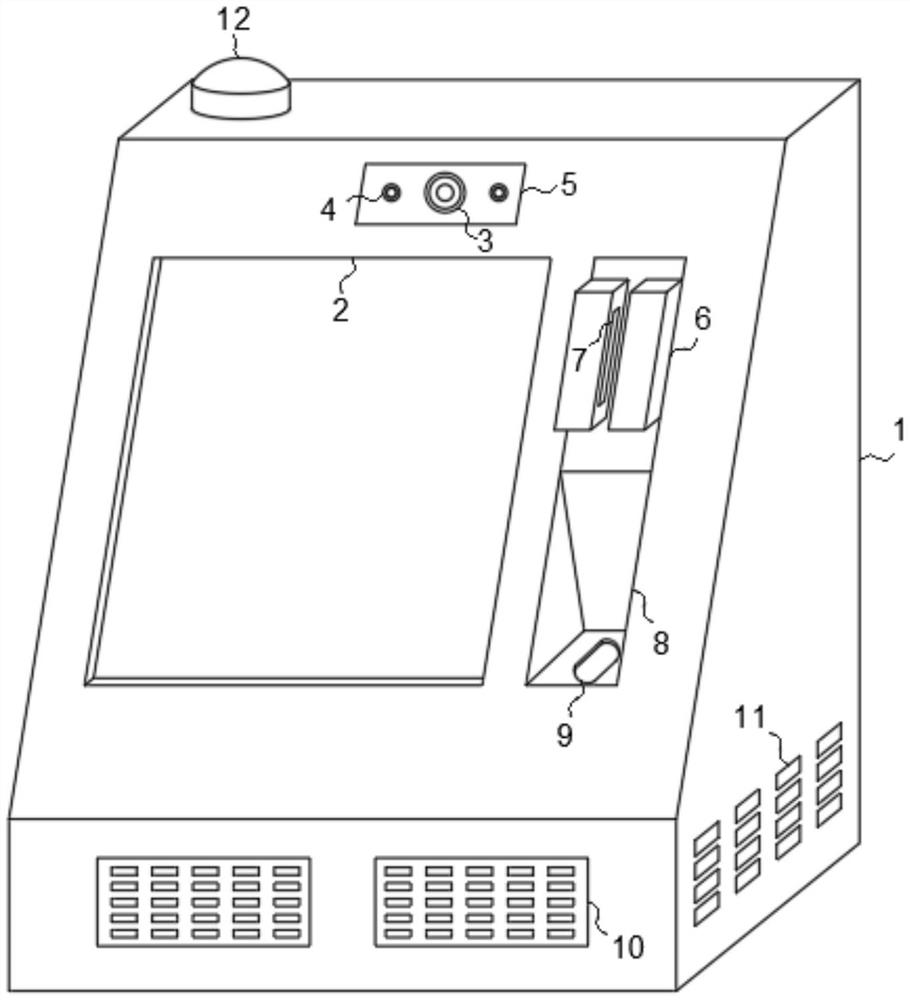
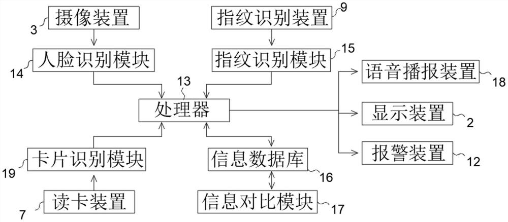
[0016] see Figure 1-2 , the present invention provides a technical solution: a substation intelligent identification system, including a housing 1 and a processor 13, the processor 13 is located inside the housing 1, a display screen 2 is provided on one side of the housing 1, and the The display screen 2 is electrically connected with the processor 13, and the display screen 2 can display the working status of the processor 13, and remind the staff of the operation steps. The top of the display screen 2 is provided with a camera 3, and the camera 3 is connected to the human body. The face recognition module 14 is electrically connected, and the face recognition module 14 is electrically connected to the processor 13. The camera 3 samples the face, and the face recognition module 14 recognizes and transmits data to the processor 13. The processor 13 compare the received data in the information database 16 through the information comparison module 17, so as to recognize the face, the outside of the camera 3 is provided with a protective plate 5, and one side of the display screen 2 is provided with a mounting seat 6, so The middle part of the mounting base 6 is provided with a card reading device 7, the card reading device 7 is electrically connected to the card identification module 19, the card identification module 19 is electrically connected to the processor 13, and the card reading device 7 can read the Work card information, a protective slot 8 is provided under the mounting base 6, a fingerprint collection device 9 is provided below the protective slot 8, and the fingerprint collection device 9 is electrically connected to the fingerprint identification module 15, and the fingerprint identification module 15 It is electrically connected with the processor 13, the processor 13 is electrically connected with the information database 16, and the information database 16 is electrically connected with the information comparison module 17, and the fingerprint collecting device 9 will collect the fingerprint and transmit it to the fingerprint identification module 15 , and the processor 13 and the information database 16 carry out the fingerprint search, thereby completing the comparison work and completing the identification. The processor 13 is provided with a cloud processing device, and the cloud processing device has a corresponding cloud processor, and the cloud processor is arranged in the monitoring room. It can be directly monitored in the monitoring room. At the same time, when the identification is performed, the number of identification failures is set to two times. If there are two failures, the alarm device will be activated immediately.
[0017] Furthermore, the camera device 3 is a camera.
[0018] Furthermore, the said fingerprint collection device 9 is a fingerprint collection board.
[0019] Furthermore, both sides of the imaging device 3 are provided with supplementary light 4, and the protective plate 5 is a transparent glass plate. The supplementary light 4 and the imaging device outside the supplementary light 4 provide a light source in the case of weak light.
[0020] Further, the housing 1 is provided with a voice broadcast device 18, the voice broadcast device 18 is a loudspeaker, and the housing 1 is provided with a loudspeaker hole 10 outside the voice broadcast device 18, and the voice broadcast device 18 can directly Announce the operation steps.
[0021] Further, an alarm device 12 is provided on the top of the housing 1, the alarm device 12 is an audible and visual alarm, the alarm device 12 is electrically connected to the processor 13, and the alarm device 12 has two identification errors. ,Send out a warning.
[0022] Furthermore, a heat dissipation window 11 is provided on one side of the housing 1 .
[0023] Although the embodiments of the present invention have been shown and described, those skilled in the art can understand that various changes, modifications and substitutions can be made to these embodiments without departing from the principle and spirit of the present invention. and modifications, the scope of the invention is defined by the appended claims and their equivalents.

PUM

no PUM

Description & Claims & Application Information

We can also present the details of the Description, Claims and Application information to help users get a comprehensive understanding of the technical details of the patent, such as background art, summary of invention, brief description of drawings, description of embodiments, and other original content. On the other hand, users can also determine the specific scope of protection of the technology through the list of claims; as well as understand the changes in the life cycle of the technology with the presentation of the patent timeline. Login to view more.

Similar technology patents

Classification and recommendation of technical efficacy words

  • Simple structure
  • Improve security performance

Microlithographic projection exposure apparatus

InactiveUS20050068499A1Simple structureReliable and low-maintenance operationProjectorsPhotomechanical exposure apparatusCamera lensPhysics
Owner:CARL ZEISS SMT GMBH
Why Eureka
Try Eureka