Atomization device with metal mesh and manufacture method thereof

An atomizing device and metal mesh technology, which is applied in the field of electronic cigarettes, can solve the problems of unusable heating wire, slow atomization speed of e-liquid, and slow heating speed of heating wire.

Active Publication Date: 2018-06-15
INNOKIN TECH
View PDF14 Cites 1 Cited by
  • Summary
  • Abstract
  • Description
  • Claims
  • Application Information

AI Technical Summary

Problems solved by technology

[0002] An electronic cigarette commonly used at present mainly includes an atomizer, a pod body, an oil storage tank, and a lower case. A power supply is installed in the lower case. The atomizer includes hair and cotton. The chemical filament provides electric energy, the chemical filament generates heat, and the cotton is used to absorb the e-liquid in the oil storage tank. The chemical filament atomizes the e-liquid absorbed by the cotton, and the atomized e-liquid generates smoke, which passes through the pod body The channel flows out for people to suck. This is generally a heating wire, which is bent in a spiral shape, and cotton is wound on the heating wire. The resistance value of this heating wire is generally fixed. Therefore, Its heating power is fixed. When high-power atomized e-liquid is needed, the voltage needs to be increased at both ends of the heating wire. However, if the voltage is too high, it is easy to burn the heating wire and cause the product to be scrapped. If the power is too low , the heating speed of the heating wire is slow. Under the condition of the same amount of e-liquid, the speed of atomizing the e-liquid is slow, and if the heating wire is damaged, the whole heating wire cannot be used.

Method used


Image

  • Atomization device with metal mesh and manufacture method thereof
  • Atomization device with metal mesh and manufacture method thereof
  • Atomization device with metal mesh and manufacture method thereof

Examples


Embodiment Construction

[0036] The following will clearly and completely describe the technical solutions in the embodiments of the present invention with reference to the accompanying drawings in the embodiments of the present invention. Obviously, the described embodiments are only some, not all, embodiments of the present invention. Based on the embodiments of the present invention, all other embodiments obtained by persons of ordinary skill in the art without making creative efforts belong to the protection scope of the present invention.

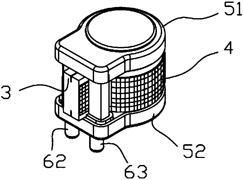
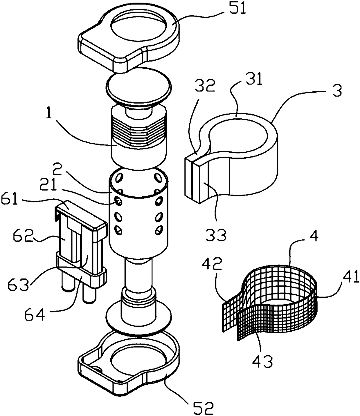
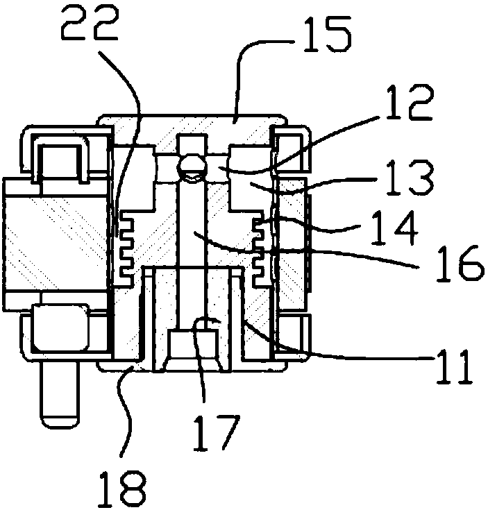
[0037] Such as Figure 1-Figure 5 , the embodiment of the present invention provides an atomizing device with a metal mesh, which includes: a main body 1, an oil inlet 11 is arranged on the lower part, an oil outlet 12 is opened on the upper part of the main body 1, and an oil outlet 12 is provided on the upper part of the main body 1. A plurality of grooves 14 are recessed on the side, and the grooves 14 are located between the oil inlet 11 and the oil outlet...


PUM


Abstract

The invention provides an atomization device with a metal mesh. The atomization device comprises a main body, and an oil inlet, an oil outlet and grooves are formed in the main body; the main body issleeved with a shell, and a plurality of oil holes are formed in the side wall of the shell; the periphery of the oil holes is sleeved with an oil guiding member; the periphery of the oil guiding member is sleeved with an atomizing net, and the atomizing net is provided with a first free end and a second free end; an upper fastening member and a lower fastening member are respectively buckled at the upper and lower portions of the main body; a first electrode and a second electrode are respectively disposed between the upper fastening member and the lower fastening member; the first free end is fixed to the first electrode, and the second free end is fixed to the second electrode. The smoke oil can be atomized in the shortest time, there is no need to increase the voltage at the two ends of the atomizing net, the structure is simple, the use is safe, and the atomization device is suitable for various high power design requirements. The shell is sleeved with the oil guiding member, theoil guiding member is sleeved with the atomizing net, and the first electrode and the second electrode are fixed, so that the manufacturing process is simple, and the operability is strong.

Description

technical field [0001] The invention relates to the field of electronic cigarettes, in particular to an atomizing device with a metal mesh and a manufacturing method thereof. Background technique [0002] An electronic cigarette commonly used at present mainly includes an atomizer, a pod body, an oil storage tank, and a lower case. A power supply is installed in the lower case. The atomizer includes hair and cotton. The chemical filament provides electric energy, the chemical filament generates heat, and the cotton is used to absorb the e-liquid in the oil storage tank. The chemical filament atomizes the e-liquid absorbed by the cotton, and the atomized e-liquid generates smoke, which passes through the pod body The channel flows out for people to suck. This is generally a heating wire, which is bent in a spiral shape, and cotton is wound on the heating wire. The resistance value of this heating wire is generally fixed. Therefore, Its heating power is fixed. When high-power...

Claims


Application Information

Patent Timeline
Patent Type & Authority Applications(China)
IPC IPC(8): A24F47/00
Inventor 谭会民乐雷
Owner INNOKIN TECH
Why Eureka
Try Eureka