A soil remediation device that can precisely control the feeding efficiency

A soil remediation and accurate technology, applied in the field of soil remediation, can solve the problems of low soil remediation efficiency, difficult to transfer and use, equipment occupying a large space, etc., to achieve the effect of improving excavation efficiency, complete functions, and improving work.

Active Publication Date: 2021-05-14
ANHUI HEKUANG MACHINERY
View PDF7 Cites 0 Cited by
  • Summary
  • Abstract
  • Description
  • Claims
  • Application Information

AI Technical Summary

Problems solved by technology

[0003] The purpose of the present invention is to provide a soil remediation device that can precisely control the feeding efficiency, so as to solve the problems in the prior art that the soil remediation efficiency is low, the equipment takes up a lot of space, and it is difficult to transfer to another site, so as to reduce the storage space, facilitate movement, The purpose of improving the repair efficiency

Method used


Image

  • A soil remediation device that can precisely control the feeding efficiency
  • A soil remediation device that can precisely control the feeding efficiency
  • A soil remediation device that can precisely control the feeding efficiency

Examples


Embodiment 1

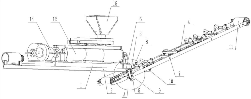
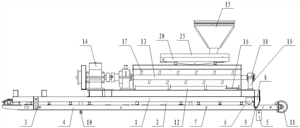
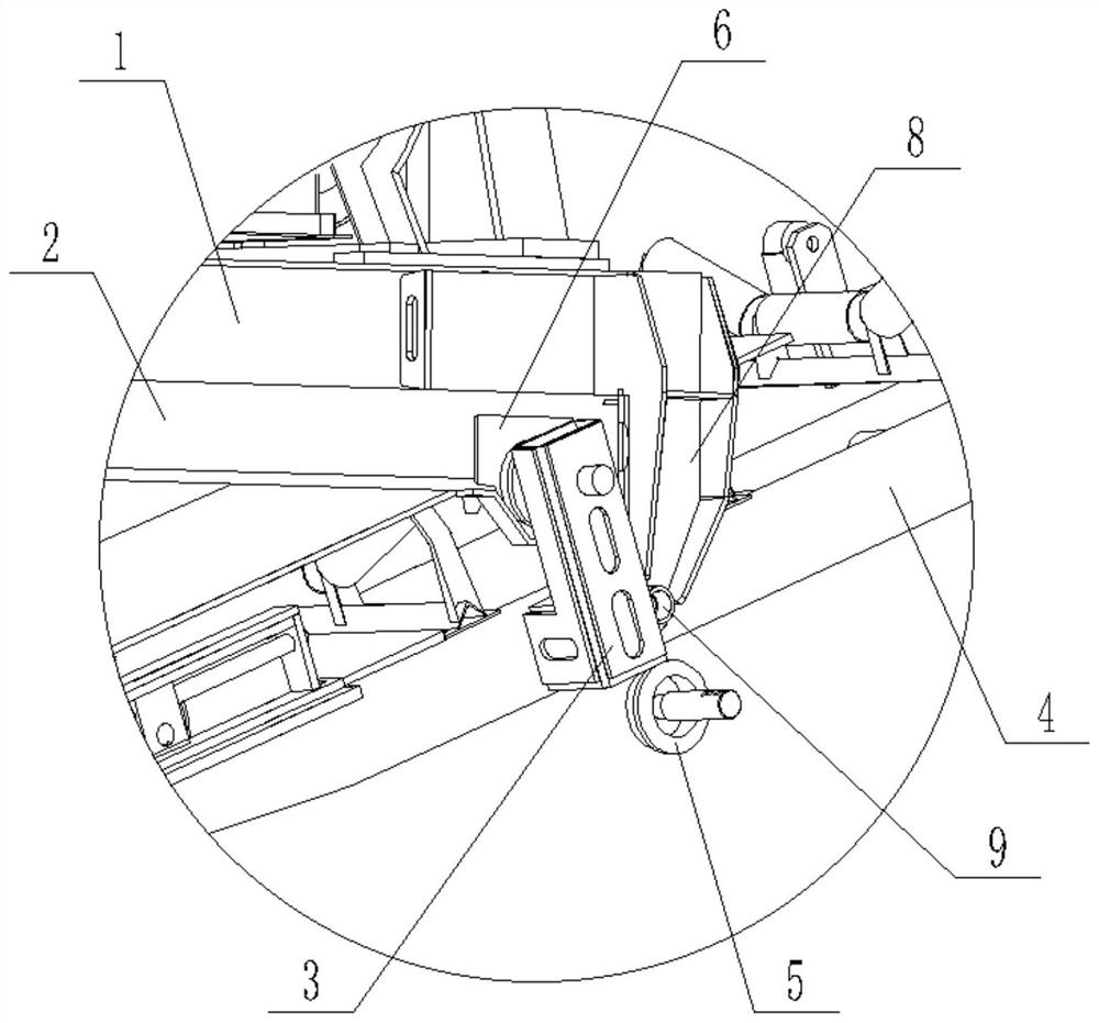
[0033] Such as Figure 1 to Figure 6 The shown soil remediation device capable of precisely controlling the feeding efficiency includes a platform body 1, the lower surface of the platform body 1 is a plane, a slideway 2 is arranged at the bottom of the platform body 1, and a first bearing is arranged on the slideway 2. A bearing can slide in the slideway 2, the first bearing is installed on the first bearing seat 3, and the first bearing seat 3 moves with the movement of the first bearing; the first bearing seat 3 and the linear transmission device 4 fixedly connected, the long axis of the linear transmission device 4 is coplanar with the long axis of the platform body 1; it also includes a support 5 connected to the lower end of the linear transmission device 4; a storage bin 12 is set on the platform body 1, and the A stirring shaft 13 is arranged in the storage bin 12, and a drive device 14 is arranged outside the storage bin 12, and the drive device 14 is used to drive th...

Embodiment 2

[0035] Such as Figure 1 to Figure 6 What is shown also includes a counterweight shaft 24 arranged on the elastic piece 21 , the counterweight shaft 24 is parallel to the rotation shaft 22 ; the upper edge of the transfer frame 20 is detachably connected to the first baffle plate 25 . The aperture of the first through hole 28>the aperture of the second through hole 30; the gap between the upper surface of the second baffle plate 27 and the lower surface of the upper partition plate 26 is 1-3mm; the two partition plates The first through holes 28 on the 26 are facing one by one. One end of the slideway 2 is provided with a positioning groove 6 , the positioning groove 6 is a trapezoidal structure with a large top and a small bottom, and the first bearing can move up and down in the positioning groove 6 . A number of first pin holes 7 are evenly distributed on the side of the linear transmission device 4, and a mounting block 8 is fixed at the end of the slideway 2, and a secon...


PUM


Abstract

The invention discloses a soil remediation device capable of precisely controlling the feeding efficiency. A slideway is arranged at the bottom of the table body, and a first bearing is arranged on the slideway; the first bearing seat is fixedly connected to the linear transmission equipment; the lower end of the linear transmission equipment is connected to a support; the platform body A storage bin is set on the top, and a stirring shaft is set in the storage bin; several blades are evenly distributed on the stirring shaft; The upper and lower openings are opened, and elastic sheets are laid in the transfer frame. One end of the elastic sheet is fixed and the other end is connected to the rotating shaft, which is driven by a frequency conversion motor; The first through holes are distributed, the baffle is driven to rotate by the motor, and the second through holes are distributed on the baffle. The invention is used to solve the problems in the prior art that the soil restoration equipment occupies a large amount of space and is difficult to be used in transition, and achieves the purpose of reducing the space occupied by storage and facilitating movement.

Description

technical field [0001] The invention relates to the field of soil remediation, in particular to a soil remediation device capable of precisely controlling the feeding efficiency. Background technique [0002] The soil is originally a natural shelter and purification treatment place for various wastes. The soil accepts pollutants, which does not mean that the soil is polluted. Only when the soil contains too many pollutants, it affects and exceeds the self-purification ability of the soil. , thus producing harmful hygienic and epidemiological effects, which indicate that the soil has been polluted. There are many reasons for soil pollution, such as industrial sludge, agricultural garbage, sewage irrigation, pollutant deposition in the atmosphere, heavy use of mineral fertilizers and pesticides containing heavy metals, and so on. Soil remediation is a technical measure to restore the normal function of polluted soil. In the soil remediation industry, there are more than one ...

Claims


Application Information

Patent Timeline
Patent Type & Authority Patents(China)
IPC IPC(8): B09C1/08B01F7/04B01F15/02
CPCB09C1/08B01F27/1125B01F27/191B01F27/70B01F35/71731Y02P70/10
Inventor 胡乾桂许家胜任启明
Owner ANHUI HEKUANG MACHINERY
Why Eureka
Try Eureka