Die-casting die structure

A die-casting mold and mold core technology, which is applied in the field of mold structure, can solve problems such as poor filling of column positions, improve the life of ejector pins and product quality, prevent ejector pins from bending or breaking, and improve quality

Active Publication Date: 2018-06-15
昆山上达精密配件有限公司
View PDF9 Cites 1 Cited by
  • Summary
  • Abstract
  • Description
  • Claims
  • Application Information

AI Technical Summary

Problems solved by technology

[0003] In order to overcome the above-mentioned defects, the present invention provides a die-casting mold structure, which can effectively solve the technical problem of poor filling of products with higher column positions

Method used


Image

  • Die-casting die structure
  • Die-casting die structure
  • Die-casting die structure

Examples


Embodiment Construction

[0030] A preferred embodiment of the present invention will be described in detail below in conjunction with the accompanying drawings. However, the scope of protection of the present invention is not limited to the following examples, that is, any simple equivalent changes and modifications made based on the patent scope of the present invention and the content of the description are still within the scope of the patent of the present invention.

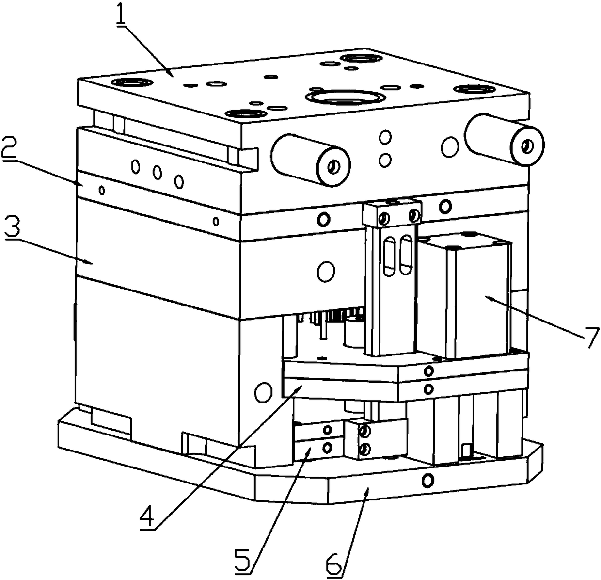
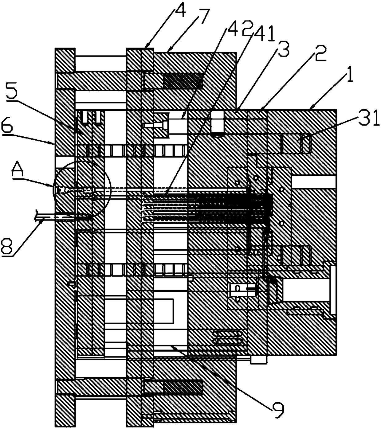
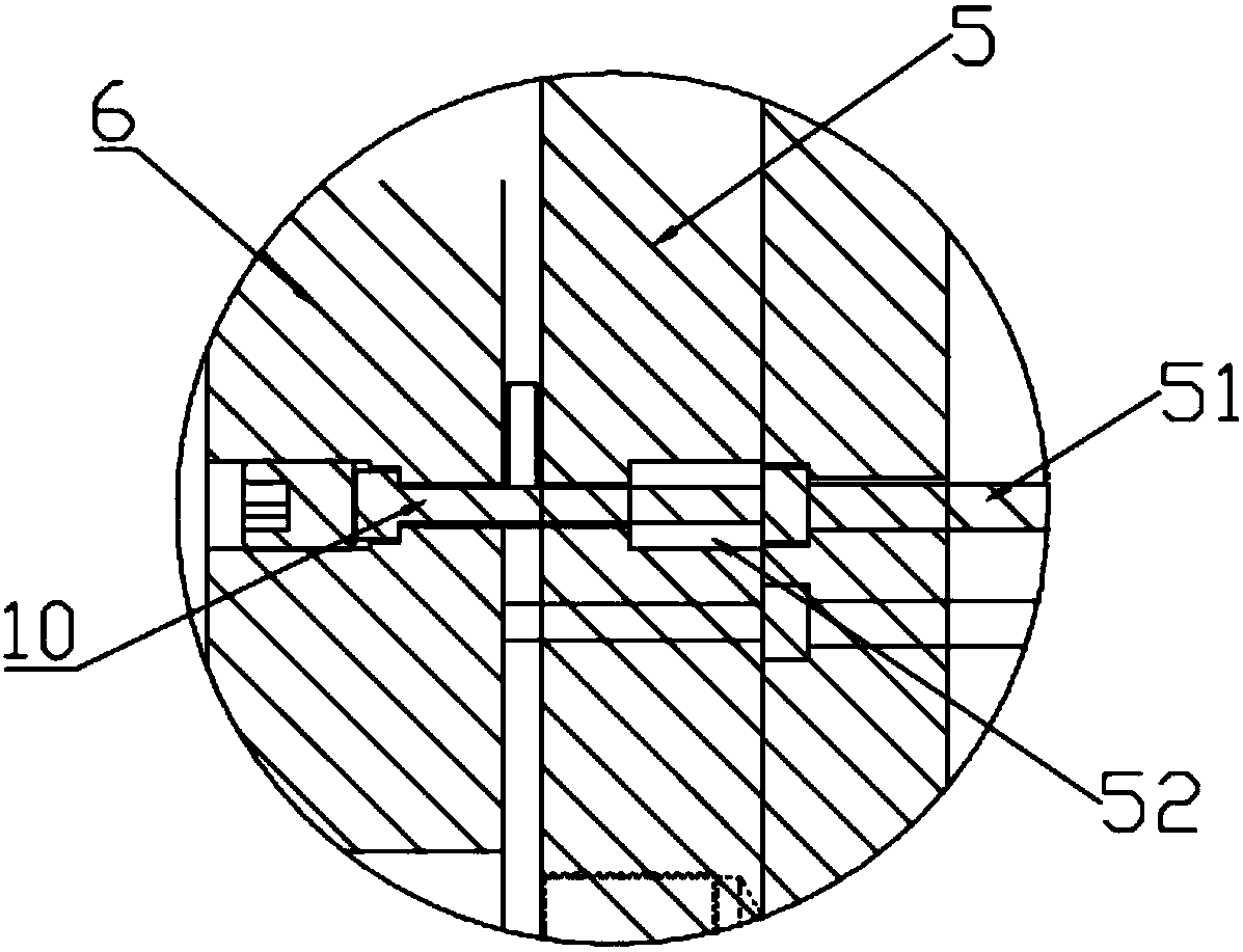
[0031] refer to Figure 1-11 , is a die-casting mold structure according to the present invention, including a front template 1, a first rear template 2, a second rear template 3, a first ejector plate 4, a second ejector plate 5 and a bottom plate 6 arranged in sequence, the A first mold core for forming products is provided between the front template and the first rear template, and a second mold core for slag discharge is provided between the first rear template and the second rear template; the first ejector plate A first thimb...


PUM


Abstract

The invention discloses a die-casting die structure. The die-casting die structure comprises a front mold plate, a first back mold plate, a second back mold plate, a first ejector plate, a second ejector plate and a bottom plate which are successively arranged. A first mold core is arranged between the front mold plate and the first back mold plate, and a second mold core is arranged between the first back mold plate and the second back mold plate; an ejector pin is arranged on the ejector plate, an oil cylinder is fixed to the second back mold plate, and the oil cylinder can drive the first ejector plate to move front and back to eject a product formed in the first mold core; the second ejector plate is fixedly connected to the first back mold plate, and an ejector rod of a die-casting machine penetrates through the bottom plate and is fixed to the second ejector plate and can drive the second ejector plate to move front and back to eject paint slag in the second mold core. Accordingto the die-casting die structure, a conventional two mold plate structure is changed to a three mold plate structure. One of the mold plates is used for forming the product while the other mold plateis used for discharging slag and ejecting the product, so that the problem that the product is not filled well when product column positions which are higher and more are available is solved, and thequality of the pressure casting products is improved.

Description

technical field [0001] The invention relates to a mold structure, in particular to a die-casting mold structure. Background technique [0002] At present, the existing die-casting molds generally include a front mold and a rear mold. The front mold core is set in the front mold, the rear mold core is set in the rear mold, and the mold is opened and closed to form products. However, due to the structure of the existing die-casting mold, the material The position, slag discharge and ejection structure are all in the rear mold core, so when the die-casting mold is used to produce products with higher column positions, due to the limitation of the product structure, the column positions will be filled when the module is opened for die-casting products Poor, resulting in the accuracy of die-casting products affected. Contents of the invention [0003] In order to overcome the above-mentioned defects, the present invention provides a die-casting mold structure, which can effect...

Claims


Application Information

Patent Timeline
Patent Type & Authority Applications(China)
IPC IPC(8): B22D17/22
CPCB22D17/22B22D17/2236Y02P70/10
Inventor 王丽坤季鸭龙
Owner 昆山上达精密配件有限公司
Why Eureka
Try Eureka