
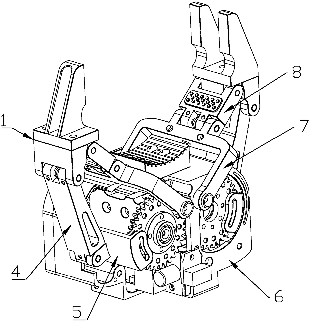
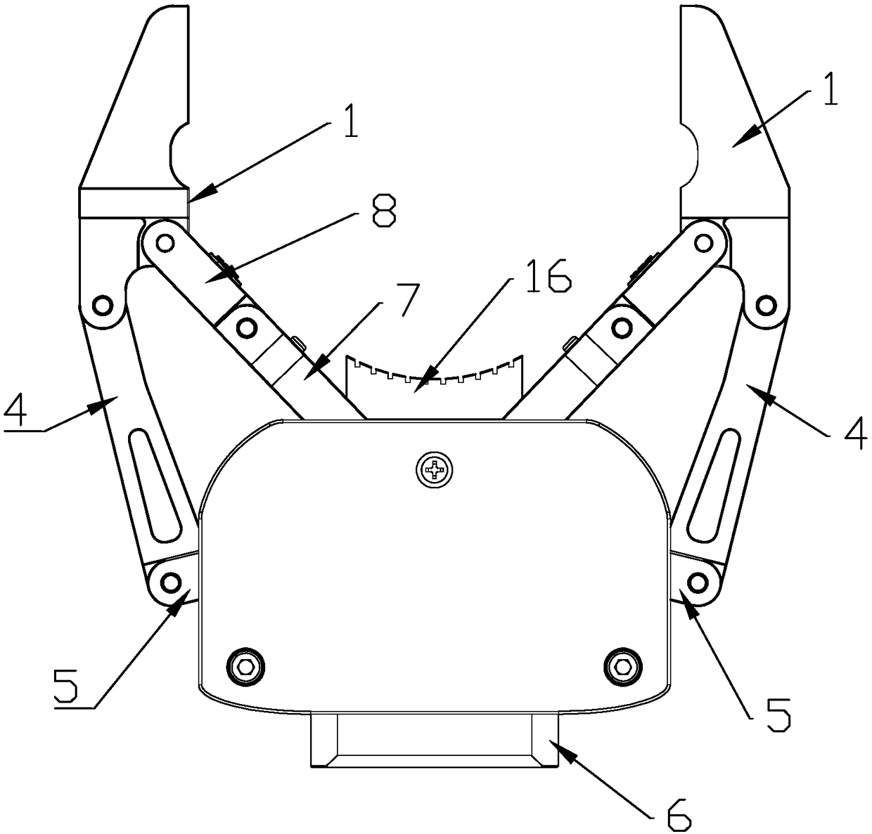
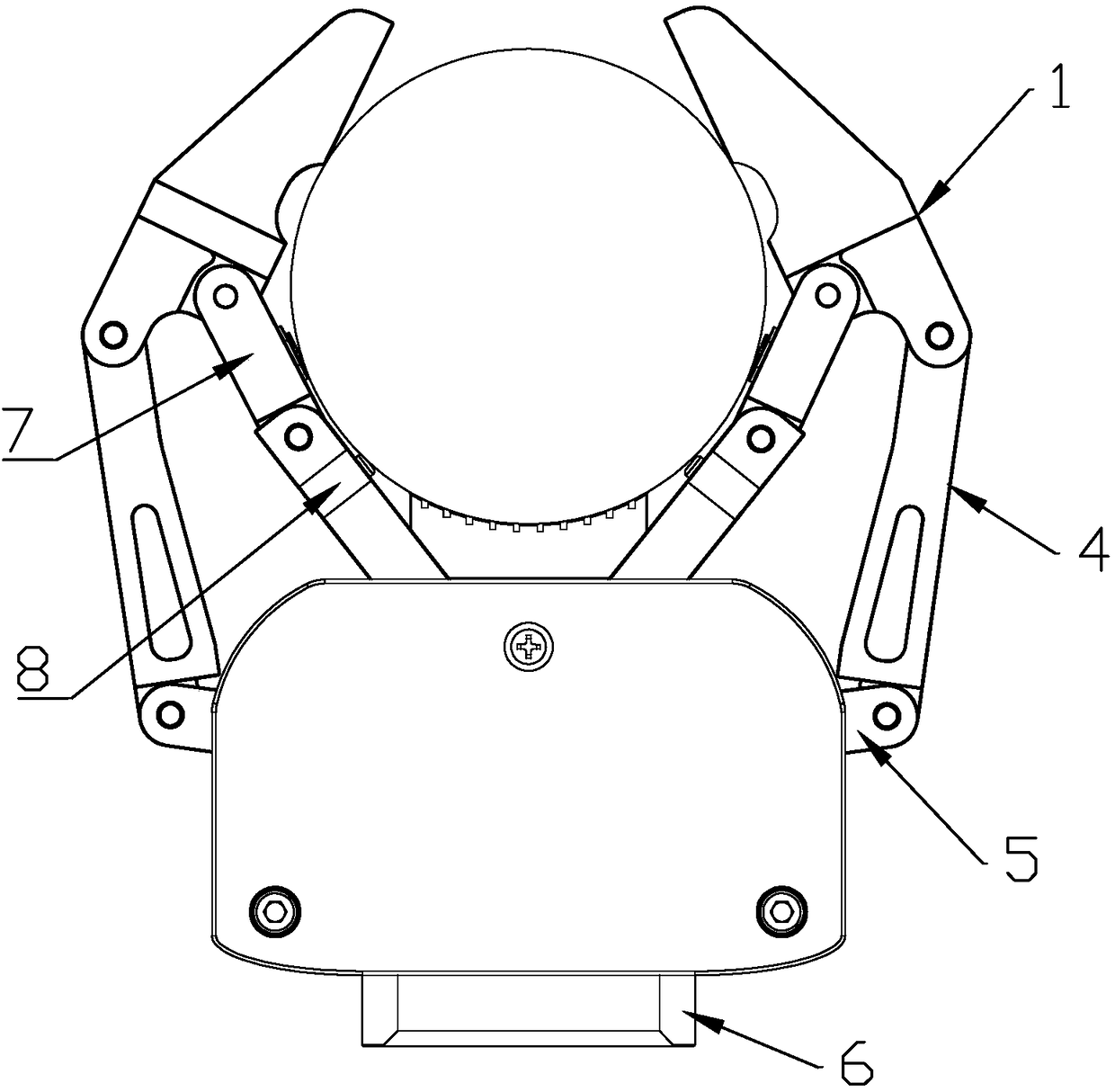
Manipulator gripper

A robot gripper and connecting rod technology, applied in the field of robots, can solve the problems of grasping failure, insufficient limit, narrow application range, etc., and achieve the effect of compact structure

Pending Publication Date: 2018-06-15
深圳市智能机器人研究院
View PDF6 Cites 4 Cited by
  • Summary
  • Abstract
  • Description
  • Claims
  • Application Information

AI Technical Summary

Problems solved by technology

However, when grasping irregular objects, it is easy to fail due to uneven contact, insufficient limit, insufficient friction, etc.
[0003] There are two ways of the existing robot clamping mechanism: 1. A pair of meshing gears drives two fingers to move. The disadvantage is that the retractable movement is as simple as scissors opening and closing, and the scope of application is narrow; 2. A pair of meshing gears drives two fingers. A group of parallel four-link finger movements, the disadvantage is that the two fingers are intelligently kept parallel or at a certain angle for clamping movement, which affects the grasping efficiency when grasping objects of different shapes

Method used


Image

  • Manipulator gripper
  • Manipulator gripper
  • Manipulator gripper

Examples


Embodiment Construction

[0021] Combine below Figure 1 to Figure 6 The present invention is further described.

[0022] The robot gripper includes a mounting frame 6 and two clamping units, the clamping units are symmetrically arranged, the mounting frame 6 is arranged with a driving device, and the clamping unit includes a clamping structure 1, and the clamping structure A driven link assembly hinged in the middle of 1 and an active link assembly hinged at the end of the clamping structure 1 . The other end of the driven link assembly is hinged to the mounting frame 6, and the other end of the active link assembly is arranged at the output end of the driving device.

[0023] The driven link assembly includes a seventh connecting rod 7 hinged to the mounting frame 6 and an eighth connecting rod 8 hinged to the clamping structure 1, the seventh connecting rod 7 and the eighth connecting rod 8 hinged between. The active link assembly includes an active member 5 connected to the output end of the dri...


PUM


Abstract

The invention discloses a manipulator gripper. The manipulator gripper comprises a mounting frame and two clamping units. A drive device is arranged on the mounting frame. Each clamping unit comprisesa clamping structure, a driven connecting rod assembly and a driving connecting rod assembly. The other end of each driven connecting rod assembly is hinged to the mounting frame. The other end of each driving connecting rod assembly is arranged at the output end of the drive device. According to the manipulator gripper, objects such as cuboid objects as well as curved-surface-shaped objects suchas cylindrical objects can be clamped by the clamping units; when the cuboid objects are clamped, the driving connecting rod assemblies are regarded as a whole, the driven connecting rod assemblies are regarded as a whole, and the two clamping units are essentially a four-connecting-rod mechanism. When the cylindrical objects are clamped, the driving connecting rod assemblies, the driven connecting rod assemblies and the clamping structures form a six-connecting-rod mechanism. The manipulator gripper can clamp objects in different shapes and can be widely applied to the technical field of robots.

Description

technical field [0001] The invention relates to the technical field of robots, in particular to a robot gripper. Background technique [0002] At present, the robot industry is developing rapidly, and the demand for robot grippers is becoming increasingly urgent. In the existing robot grippers, gear transmission is generally used to realize double-finger counter-rotating clamping and gear-driven four-link counter-rotating horizontal clamping. However, when grasping irregular objects, it is easy to fail due to reasons such as uneven contact, insufficient limit, and insufficient friction. [0003] There are two ways of the existing robot clamping mechanism: 1. A pair of meshing gears drives two fingers to move. The disadvantage is that the retractable movement is as simple as scissors opening and closing, and the scope of application is narrow; 2. A pair of meshing gears drives two fingers. The disadvantage of the parallel four-link finger movement is that the two fingers ar...

Claims


Application Information

Patent Timeline
IPC IPC(8): B25J15/02B25J15/08
CPCB25J15/0213B25J15/08
Inventor 黄佳亮毕盛杨阳张家维
Owner 深圳市智能机器人研究院
Learn More