
Ship high-stress joint structure

A node structure, high stress technology, applied in the direction of ship hull, hull parts, ship construction, etc., can solve the problems of difficult to meet requirements, increase the weight of the structure, etc., to reduce the weight of the structure, reduce the stress, and facilitate the production and installation.

Active Publication Date: 2018-06-15
HUDONG ZHONGHUA SHIPBUILDINGGROUP
View PDF6 Cites 1 Cited by
  • Summary
  • Abstract
  • Description
  • Claims
  • Application Information

AI Technical Summary

Problems solved by technology

Taking the joint of the lower sloping side plate, platform slab, inner longitudinal wall plate and floor plate of an LNG carrier as an example, the traditional design method of the joint at this position is that the platform slab protrudes outside the inner longitudinal wall plate, and the lower sloping side plate connects At the intersection of the platform slab and the inner longitudinal wall slab, when the stress of the node is too high, the thickness of the slab in the adjacent area of ​​the node is generally increased to reduce the stress, or the material grade of the slab in the adjacent area of ​​the node is increased to increase the stress. When these methods still cannot reduce the stress at the joints below the allowable stress; for such a situation where the stress is too high, usually add small ribs or Brackets are used to reduce the joint stress. The above methods will increase the weight of the structure, especially in some special cases, such as the single-tank loading condition of a double row tank tanker, which will cause the joint stress to be too high, and only increase the plate thickness or small ribs It is also difficult to reduce the stress within the allowable range. At this time, this kind of node design is difficult to meet the requirements

Method used


Image

  • Ship high-stress joint structure
  • Ship high-stress joint structure

Examples


Embodiment Construction

[0012] In order to make the object, technical solution and advantages of the present invention clearer, the present invention is described below through specific embodiments shown in the accompanying drawings. It should be understood, however, that these descriptions are exemplary only and are not intended to limit the scope of the present invention. Also, in the following description, descriptions of well-known structures and techniques are omitted to avoid unnecessarily obscuring the concept of the present invention.

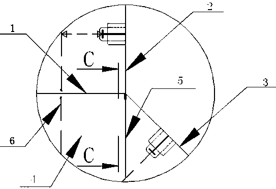
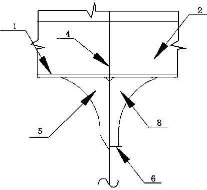
[0013] combine figure 1 To illustrate this embodiment, the ship's high-stress node structure of the present invention includes a platform plate 1, a longitudinal bulkhead plate 2, a sloping side plate 3, a floor plate 4 and a bracket.

[0014] The platform plate 1 is arranged horizontally, the longitudinal bulkhead plate 2 is vertically arranged on the platform plate 1, and the inclined side plate 3 is arranged obliquely at the junction of the platform plate ...


PUM


Abstract

The invention discloses a ship high-stress joint structure which comprises a horizontally-arranged platform plate, longitudinal cabin wall plates vertically arranged on the platform plate in the longitudinal direction, oblique side plates obliquely arranged on the intersections of the platform plate and the longitudinal cabin wall plates, rib plates perpendicular to the platform plate and the longitudinal cabin wall plates, and wrist plates fixedly connected with the lower surfaces of the rib plates and the platform plate. The lower ends of the longitudinal cabin wall plates stretch out from the connecting positions of the longitudinal cabin wall plates and the platform plate, and cutting grooves used for enabling the longitudinal cabin wall plates to penetrate through are formed in the corners of the rib plates. According to the ship high-stress joint structure, the structure is simple, on-site manufacturing and mounting are convenient, the lower ends of the longitudinal cabin wall plates stretch out from the connecting positions of the longitudinal cabin wall plates and the platform plate by 30-50 mm, the rib plates and the wrist plates are arranged, thus joint stress can be downwards transmitted, the situation of stress concentration at a joint is remarkably reduced accordingly, the stress at the joint is greatly reduced, and the structural weight of a ship is effectively reduced.

Description

technical field [0001] The invention relates to the technical field of ship building, in particular to a ship high stress node structure. Background technique [0002] In modern ship design, in order to save fuel consumption, increase cargo capacity, and reduce construction costs, the concept of lightweight structure design is generally pursued. However, for the safety of ship operation, under the requirements of the codes and conventions, the plate thickness and structural members cannot be reduced arbitrarily. Therefore, to ensure that the requirements of the codes and conventions are met, reducing the structural weight as much as possible is an important goal of structural design. [0003] In the design of ship structures, there are often large stresses in the nodes at the structural mutations, such as the nodes at the intersection of the lower inclined side plate and the inner bottom plate or inner longitudinal wall plate, and other similar nodes have greater profits. T...

Claims


Application Information

Patent Timeline
IPC IPC(8): B63B3/70
CPCB63B3/70
Inventor 韩松标姜甲志王小宁司昭
Owner HUDONG ZHONGHUA SHIPBUILDINGGROUP
Learn More