Supercharge Your Innovation With Domain-Expert AI Agents!

Rotary motion system of end portion space

A technology of rotary motion and space, applied in the track field, can solve the problems of low reliability, large number of motors, high cost, etc., and achieve the effect of improving the operation efficiency of the container and the smooth operation process

Pending Publication Date: 2018-06-15
CRRC CHANGCHUN RAILWAY VEHICLES CO LTD +1
View PDF0 Cites 0 Cited by
  • Summary
  • Abstract
  • Description
  • Claims
  • Application Information

AI Technical Summary

Problems solved by technology

However, the rotary technology using the power drum has the following defects: 1) the installation space is large, and it is not suitable for the interior of the rail locomotive; 2) the number of motors required is large, the cost is large, and the reliability is low

Method used


Image

  • Rotary motion system of end portion space
  • Rotary motion system of end portion space
  • Rotary motion system of end portion space

Examples


Embodiment Construction

[0054] Specific embodiments of the present invention will be described below in conjunction with the accompanying drawings.

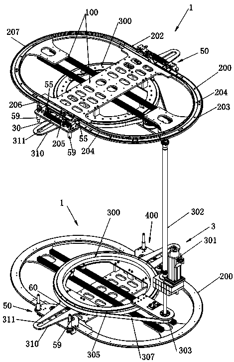
[0055] Such as figure 1 As shown, the end space rotary motion system according to a specific embodiment of the present invention includes two sets of rotary motion devices 1 and a drive mechanism 3, wherein the two sets of rotary motion devices 1 are arranged symmetrically up and down as mirror images, and the drive mechanism 3 includes servo motors 301 and Drive shaft 302 driven by servo motor 301 .

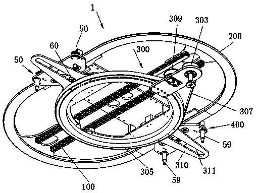
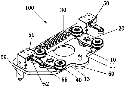
[0056] Such as figure 2 As shown, each rotary motion device 1 includes a mounting frame 100 , a rotary track 200 , a transmission mechanism 300 and a pair of pulley devices 400 . The installation frame 100 is fixedly installed in the end space, which may be the space at both ends of the track cargo box in this embodiment; the rotary track 200 is installed on the installation frame 100, and it has a straight line section located on both sides in paralle...


PUM


Abstract

The invention provides a rotary motion system of an end portion space. The rotary motion system of the end portion space includes two sets of rotary motion devices and driving mechanisms, wherein thetwo sets of rotary motion devices are symmetrically arranged in a mirror image mode up and down. Each rotary motion device includes a mounting frame, a rotary rail, a transmission mechanism and a pairof sliding trolley devices. The rotary rail is provided with a roller groove channel which is composed of a socket groove channel, a release groove channel and a road changing channel. The transmission mechanism includes a pair of fork with fork grooves. The sliding trolley devices are provided with sliding trolley seats, road changing rollers, gear rack driving structures, and pins driven by thegear rack driving structures. When the road changing rollers move from the release groove channel to the socket groove channel via the road changing groove or move from the socket groove channel to the release groove channel, the pins move from the inward retracted release position to the outward extended insertion position or from the outward extended insertion position to the inward retracted release position, so that containers to be delivered are inserted or released. The rotary motion system of the end portion space has high turnover efficiency in a narrow space.

Description

technical field [0001] The invention relates to the technical field of rails, and more specifically relates to an end space rotary motion system that converts linear motion into end rotary motion. Background technique [0002] At present, power rollers are usually installed in the railway carriages to complete the conversion of objects from linear motion to circular motion, and to change the direction of motion of objects by 180°. However, the rotary technology using the power drum has the following defects: 1) the installation space is large, and it is not suitable for the interior of the railway locomotive; 2) the number of motors required is large, the cost is high, and the reliability is low. Contents of the invention [0003] Therefore, it would be beneficial for the present invention to provide an end space rotary motion system that converts the turnover box from linear motion to circular motion in a narrow space and changes the linear motion direction of the tur...

Claims


Application Information

Patent Timeline
Patent Type & Authority Applications(China)
IPC IPC(8): B65G35/00B61D47/00
CPCB61D47/00B65G35/00
Inventor 刘琨董涛涛李宏伟孙广艳卢世伟吴胜标任海李忠宝
Owner CRRC CHANGCHUN RAILWAY VEHICLES CO LTD
Features
  • R&D
  • Intellectual Property
  • Life Sciences
  • Materials
  • Tech Scout
  • Unparalleled Data Quality
  • Higher Quality Content
  • 60% Fewer Hallucinations
Learn More