Metal ingot clamp

A technology of metal ingots and fixtures, which is applied in the stacking of objects, unstacking of objects, transportation and packaging, etc., which can solve the problems of inconvenient operation and complex ingot mechanism.

Inactive Publication Date: 2018-06-15
ZHUZHOU FLASHLIGHT IND FURNACE
View PDF6 Cites 0 Cited by
  • Summary
  • Abstract
  • Description
  • Claims
  • Application Information

AI Technical Summary

Problems solved by technology

[0004] In view of this, the object of the present invention is to provide a metal ingot clamp, which can effectively solve the problems of complex ingot code mechanism and inconvenient operation

Method used


Image

  • Metal ingot clamp
  • Metal ingot clamp
  • Metal ingot clamp

Examples


Embodiment Construction

[0025] The embodiment of the invention discloses a metal ingot clamp, which can effectively solve the problems of complex ingot coding mechanism and inconvenient operation.

[0026] The following will clearly and completely describe the technical solutions in the embodiments of the present invention with reference to the accompanying drawings in the embodiments of the present invention. Obviously, the described embodiments are only some, not all, embodiments of the present invention. Based on the embodiments of the present invention, all other embodiments obtained by persons of ordinary skill in the art without making creative efforts belong to the protection scope of the present invention.

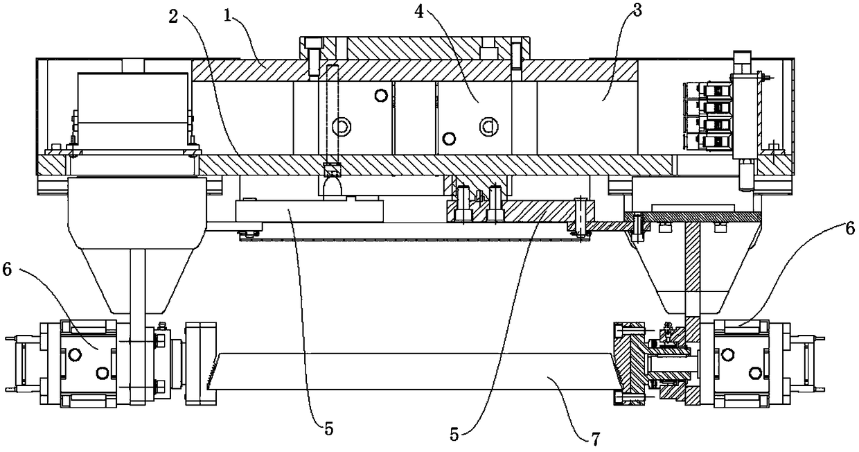
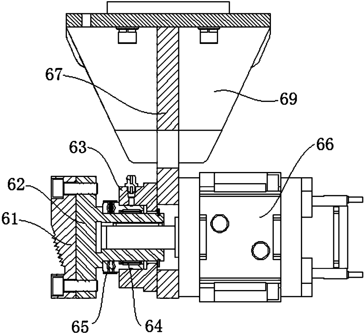
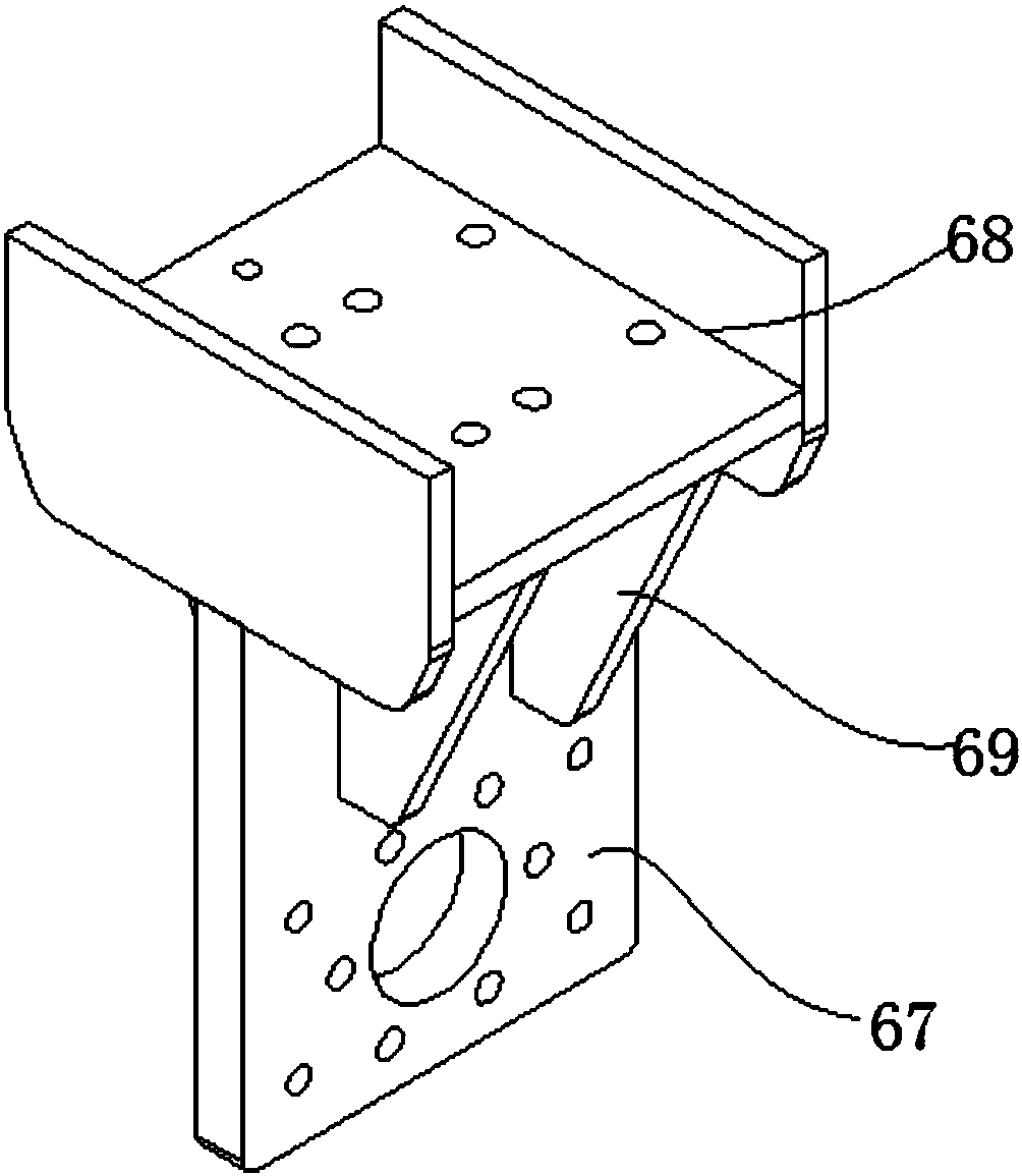
[0027] see Figure 1-Figure 3 , figure 1 Schematic diagram of the structure of the metal ingot clamp provided for the embodiment of the present invention; figure 2 Schematic diagram of the structure of the gripper provided by the embodiment of the present invention; image 3 Schematic...


PUM


Abstract

The invention discloses a metal ingot clamp. The metal ingot clamp comprises an installing seat, a clamp set and a driving device installed on the installing seat. The driving device can drive two clamp hands of the clamp set to move toward each other in order to clamp a metal ingot. Each clamp hand comprises a clamping part, a clamping seat and an overturning mechanism installed on the clamping seat to drive the clamping part to rotate. The extending direction of the rotary axis of each clamping part is consistent with the clamping direction of the clamp set. The rotary axes of the two clamphands of the clamp set are located on the same straight line. The clamping seats are in transmission connection with the driving end of the driving device. An ingot overturning mechanism is integratedon the metal ingot clamp, independent use of the ingot overturning mechanisms is avoided, the overall size can be effectively reduced, and uniform control operation of a stacking system is facilitated. In a word, by means of the metal ingot clamp, the problem that an ingot stacking mechanism is complex and inconvenient to operate can be effectively solved.

Description

technical field [0001] The invention relates to the technical field of transportation equipment, and more specifically, relates to a metal ingot clamp. Background technique [0002] In the non-ferrous smelting industry, such as zinc ingot automatic stacking line, antimony ingot automatic stacking line and other automatic production lines, the current domestic advanced stacking system uses industrial robots for stacking. Due to the form of ingot stacking, some ingots need to be turned over during the stacking process, and the fixtures installed on the existing industrial robots only have the clamping function, so it is necessary to add a mechanical ingot turning mechanism in the stacking line. Turning over by turning one end of the ingot, the ingot turning mechanism is unstable, prone to jamming of the ingot, many faults, low efficiency, and also brings a lot of noise. [0003] To sum up, how to effectively solve the problem of complex code spindle mechanism and inconvenient...

Claims


Application Information

Patent Timeline
IPC IPC(8): B65G61/00
CPCB65G61/00
Inventor 黄涛汤文远熊家政
Owner ZHUZHOU FLASHLIGHT IND FURNACE
Why Eureka
Try Eureka