
Compensation rail in-situ lifting suspension monorail turnout system

A technology of suspending monorail and compensating rail, which is applied in the field of rail transit, can solve the problems of large and complex structure of turnout, and achieve the effect of reducing cost, simplifying driving device and reducing the weight of turnout

Active Publication Date: 2018-06-15
CHINA RAILWAY ERYUAN ENG GRP CO LTD
View PDF11 Cites 2 Cited by
  • Summary
  • Abstract
  • Description
  • Claims
  • Application Information

AI Technical Summary

Problems solved by technology

[0004] The purpose of the present invention is to overcome the disadvantages of the existing suspended single track turnout structure in the prior art that the structure is complex and the turnout is huge, and to provide a compensation rail in-situ lifting type suspended single track turnout system

Method used


Image

  • Compensation rail in-situ lifting suspension monorail turnout system
  • Compensation rail in-situ lifting suspension monorail turnout system
  • Compensation rail in-situ lifting suspension monorail turnout system

Examples


Embodiment 1

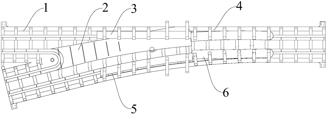
[0047] Such as Figure 1-Figure 2 As shown, a compensation rail in-situ lifting suspension single-track switch system includes a movable rail 2 connected to the turnout beam body 1, and a vertical compensation rail 3 and a lateral compensation rail 5 that can be raised and lowered in situ, and also includes The vertical correction rail 4 and the lateral correction rail 6 hinged on the turnout beam body 1, the movable rail 2 can be lifted and rotated left and right, and can be pressed and positioned after rotating to a specified position. The straight correction rail 4 and the lateral correction rail 6 can rotate respectively relative to the turnout beam body 1, and the straight correction rail 4 and the lateral correction rail 6 are rotated by a correction rail drive mechanism, and the correction rail The driving mechanism includes a correction rail electric push rod and a correction rail connection hinge.

[0048] The movable rail 2 is provided with a movable rail front end ...

Embodiment 2

[0064] Such as Figure 10-Figure 13 As shown, the difference between this embodiment and Embodiment 1 is that a different compensation rail in-situ lifting mechanism is used. The compensation rail in-situ elevating mechanism 7 in this embodiment includes a lower base 710 , a crankshaft 711 and an upper connecting seat 712 , and the upper surface of the lower base 710 is provided with a groove 713 capable of accommodating the upper connecting seat 712 .

[0065] The upper connecting seat 712 is connected to the compensation rail, at least one crankshaft 711 is hinged between the lower base 710 and the upper connecting seat 712, and each crankshaft 711 includes two crank rods hinged to each other, The lower base 710 is provided with two types of stoppers 79 compatible with the crankshaft 711, the two types of stoppers 79 are respectively angled stoppers 791 and oblique stoppers 792, and one side of the compensation rail is also provided with There is a drive locking device 11 f...


PUM


Abstract

The invention discloses a compensation rail in-situ lifting suspension monorail turnout system, which includes a movable rail connected to a turnout beam body, a straight compensation rail and a lateral compensation rail which are capable of lifting in situ, and also includes a straight repair rail and a lateral repair rail which are connected to the turnout beam body in hinge. The movable rail can be lifted and rotated left and right, and can be rotated to specific position to achieve compression and fixation. The compensation rail in-situ lifting suspension monorail turnout system has the advantages that the turnout utilizes the compensation rail capable of lifting in situ and the movable rail capable of lifting and rotating left and right, thereby greatly reducing motion space of the turnout compensation rail, simplifying the turnout beam structure to further reduce width of the turnout, reducing deadweight of the turnout and needed steel quantity, improving system reliability, andreducing cost of the turnout system.

Description

technical field [0001] The invention relates to the technical field of rail transit, in particular to a compensating rail in-situ lifting type suspension single track switch system. Background technique [0002] Suspended monorail train is a means of transportation in which trains are suspended below the track, and is suitable for transportation in small and medium-sized cities. Since the suspension of the monorail transit empty track moves the ground traffic to the air, it can alleviate the urban traffic problems without expanding the existing road facilities in the city, overcome the disadvantages of other rail transit systems, and has outstanding advantages in construction and operation. [0003] The turnout structure of the suspended monorail transportation system is complex, with many movable parts and a large number of driving devices, resulting in cumbersome systems, large turnout beams, and difficult processing and installation, which is not conducive to large-scale ...

Claims


Application Information

Patent Timeline
Patent Type & Authority Applications(China)
IPC IPC(8): E01B25/26B61B13/04
CPCE01B25/26B61B13/04
Inventor 李忠继徐银光林红松代丰颜华杨吉忠余浩伟胡连军蔡文锋徐浩冯读贝
Owner CHINA RAILWAY ERYUAN ENG GRP CO LTD
Learn More