
Verification device for nitriding furnace ammonia gas decomposition rate and verification method thereof

A verification method and a verification device technology, which are applied in the field of chemical heat treatment, can solve problems such as waste products, affecting product quality, and blocking the tail gas collection pipeline of hydrogen analyzers.

Inactive Publication Date: 2018-06-15
AECC AVIATION POWER CO LTD
View PDF7 Cites 2 Cited by
  • Summary
  • Abstract
  • Description
  • Claims
  • Application Information

AI Technical Summary

Problems solved by technology

[0003] However, due to the long-term use of the equipment, dust and residual crystals after the cracking of tetrachlorethylene will be generated, and the tail gas collection pipeline of the hydrogen analyzer will be blocked, causing the ammonia decomposition rate in the furnace measured by the hydrogen analyzer to deviate from the actual value, seriously Affect the quality of the product, or even cause waste

Method used


Image

  • Verification device for nitriding furnace ammonia gas decomposition rate and verification method thereof

Examples


Embodiment 1

[0040] The verification of the ammonia decomposition rate was carried out under the condition that the temperature of the nitriding furnace was 600°C.

[0041] Firstly, the calibration body of the present invention is communicated with the gas collection pipeline on the nitriding furnace grate pipeline; then the ammonia decomposition rate obtained by the calibration body of the method of the present invention is 80%, and the hydrogen analysis of the nitriding furnace exhaust pipeline is connected The ammonia decomposition rate obtained by the instrument is 80%; it shows that the data of the hydrogen analyzer is correct.

Embodiment 2

[0043] The verification of the ammonia decomposition rate is carried out under the condition that the temperature of the nitriding furnace is 550°C.

[0044] First, the calibration body of the present invention is communicated with the gas collection pipeline on the nitriding grate pipeline; then the ammonia decomposition rate obtained by the calibration body of the method of the present invention is 79.5%, and the hydrogen analysis of the nitriding furnace exhaust pipeline is connected The ammonia decomposition rate obtained by the instrument is 80%; it shows that the data of the hydrogen analyzer is correct.

Embodiment 3

[0046] The ammonia decomposition rate was verified when the temperature of the nitriding furnace was 600°C.

[0047] First, the calibration body of the present invention is communicated with the gas collection pipeline on the nitriding grate pipeline; then the ammonia decomposition rate obtained by the calibration body of the method of the present invention is 60%, and the hydrogen analysis of the nitriding furnace exhaust pipeline is connected The ammonia decomposition rate obtained by the instrument is 63%; it shows that the data of the hydrogen analyzer is wrong, and the hydrogen analyzer needs to be calibrated, and the gas filter of the hydrogen analyzer should be cleaned to clear the impurities in the gas filter, thereby improving Measurement accuracy of hydrogen analyzers.

[0048] By using the device and the verification method of the invention, the measurement results of the hydrogen analyzer can be monitored in real time to ensure that the product quality is monitored...


PUM


Abstract

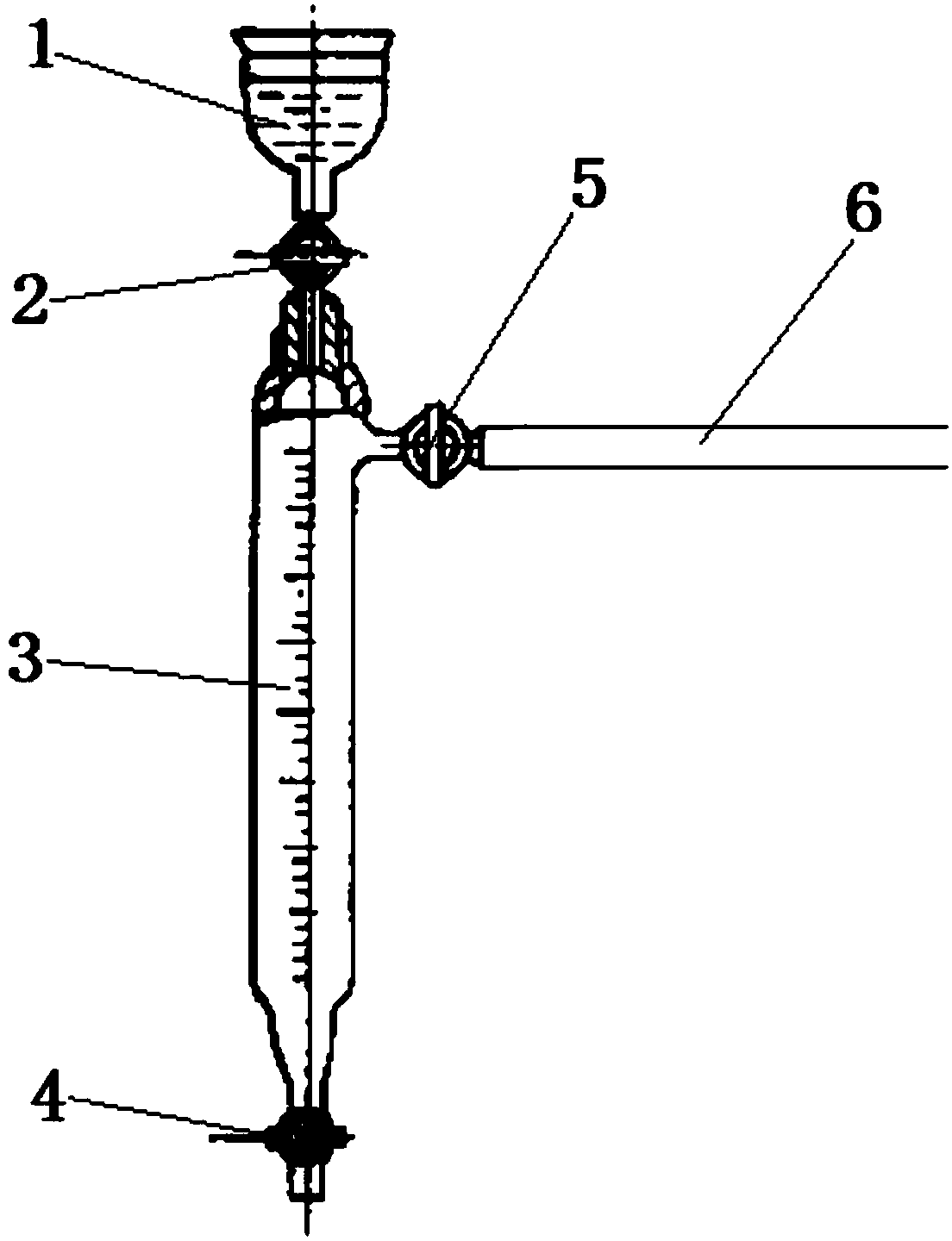
The invention discloses a verification device for nitriding furnace ammonia gas decomposition rate and a verification method thereof. Specifically, a nitriding furnace exhaust pipeline is equipped with a gas acquisition pipeline, the gas acquisition pipeline is connected to a verification body, the nitriding furnace exhaust pipeline is also connected to a hydrogen analyzer, wherein the verification body includes a communicating pipe, one end of the communicating pipe is communicated with the gas acquisition pipeline, and the other end is communicated with a measuring cylinder through a third valve. The top opening of the measuring cylinder is communicated with a water container through a first valve, and the bottom opening of the measuring cylinder is equipped with a second valve. The verification device and verification method provided by the invention can achieve rapid detection of ammonia gas decomposition rate and comparison with the hydrogen analyzer reading, and can monitor whether the hydrogen analyzer reading is correct in real time.

Description

technical field [0001] The invention belongs to the technical field of chemical heat treatment; in particular, it relates to a verification device and a verification method for the ammonia decomposition rate of a nitriding furnace. Background technique [0002] The hydrogen analyzer is a precision instrument for real-time measurement of the ammonia decomposition rate in the chemical heat treatment equipment, and its measured value directly determines the quality of the product. Take the NX-815S controlled atmosphere numerically controlled nitriding furnace of NITREX Company as an example. The principle is to decompose NH in the furnace 3 NH formed 3 , N 2 and H 2 The atmosphere is collected and the H in the unit volume is tested 2 Content, so as to calculate the ammonia decomposition rate in the furnace, and feed the data back to the PLC and industrial computer, and adjust the mass flow meter (MFC) through the industrial computer to achieve the purpose of adjusting the a...

Claims


Application Information

Patent Timeline
IPC IPC(8): G01N25/18
Inventor 殷开山陈红岩古宏博王军联雷勇王瑞刘敏赵闯
Owner AECC AVIATION POWER CO LTD
Learn More