Method for identifying frequency response function of split-free substructure based on in-situ measurement frequency response function

A frequency response function, in-situ measurement technology, applied in complex mathematical operations and other directions, can solve the problem of inability to calculate the frequency response function between degrees of freedom, to improve operability and analysis efficiency, improve prediction accuracy, and engineering applicability strong effect

Inactive Publication Date: 2018-06-15
SHANGHAI JIAO TONG UNIV
View PDF6 Cites 7 Cited by
  • Summary
  • Abstract
  • Description
  • Claims
  • Application Information

AI Technical Summary

Problems solved by technology

[0003] Aiming at the above-mentioned deficiencies in the prior art, the present invention proposes a method for identifying frequency response functions of molecular structures without dismantling based on in-situ measurement of frequency response functions. Based on the "source-path-acceptor" model, the frequency response function of coupled machinery is used to predict Deco

Method used


Image

  • Method for identifying frequency response function of split-free substructure based on in-situ measurement frequency response function
  • Method for identifying frequency response function of split-free substructure based on in-situ measurement frequency response function
  • Method for identifying frequency response function of split-free substructure based on in-situ measurement frequency response function

Examples


Embodiment 1

[0026] Such as figure 1 As shown, this embodiment includes the following steps:

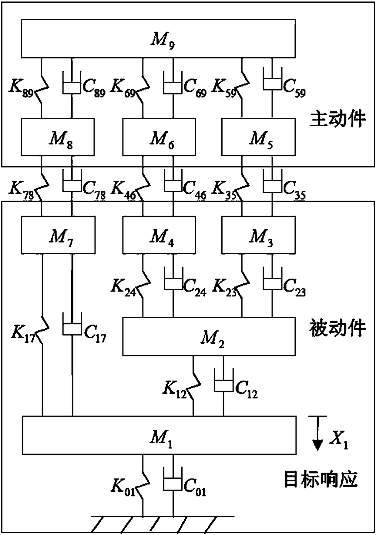
[0027] Step one, to figure 2 The discrete mechanical system shown includes active parts and passive parts, and the active part consists of four mass blocks M 5 , M 6 , M 8 , M 9 Composition, the passive part consists of 5 mass blocks M 1 ~ M 4 , M 7 Composition, there are 3 transmission paths K between the active part and the passive part 35 、K 46 、K 78 , the mass M 3 , M 4 and M 7 is the coupling point on the passive side, and the mass M 5 , M 6 , M 8 is the coupling point on the side of the active part, and the mass M 1 The displacement is the target response, there are 7 measurement points in total, and the analysis frequency range is 1-250Hz.

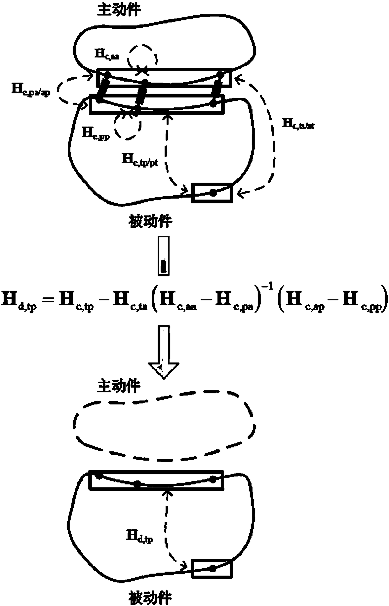
[0028] Step 2. Measure the frequency response function of the coupling mechanical system: measure the frequency response function matrix H of the active part of the coupling point c,aa , The frequency response function matrix H of th...

Embodiment 2

[0033] Such as Figure 4 As shown, the present embodiment has shown the simple physical model of vehicle body, and this model comprises vehicle body (passive parts, such as Figure 4 (a) shown) and "engine" bracket (active parts, such as Figure 4 As shown in (c), the bracket is connected to the vehicle body through three rubber suspensions. The experimental device is as follows Figure 4 (b) shown.

[0034] This embodiment includes the following steps:

[0035] Step 1. Determine the measurement point and analyze the frequency range: record the suspension points on the side of the active part as a1, a2 and a3, and the suspension points on the side of the passive part as p1, p2 and p3. The schematic diagram of the suspension and the global coordinate system are as follows: Figure 5 shown. The target point is a point (one-way) vibration response on the right side of the vehicle body, denoted as t. Only the translational degrees of freedom of the suspension points are consi...


PUM


Abstract

Disclosed is a method for identifying a frequency response function of a split-free substructure based on an in-situ measurement frequency response function. First, components in a mechanical system are classified into active components, passive components and elastic components, a coupled frequency response function matrix is established, and then a frequency response function of the decoupled mechanical system is obtained based on a passive component frequency response function prediction formula. The method predicts a decoupled mechanical frequency response function by adopting a coupled mechanical frequency response function based on a "source-path-acceptor" model, thereby overcoming the problem that the existing technology cannot calculate the frequency response function between random degrees of freedom of the mechanical substructure, improving the calculation precision of the frequency response function and laying a foundation for vibration transfer path analysis of the mechanical system.

Description

technical field [0001] The invention relates to a technology in the field of mechanical vibration analysis and detection, in particular to a method for identifying frequency response functions of molecular structures without dismantling based on in-situ measurement of frequency response functions. Background technique [0002] Transfer Path Analysis (TPA) is widely used to analyze and deal with vibration and noise problems of complex mechanical systems. Through TPA, the excitation source can be identified and quantified, the path of energy transfer from the excitation source to the target point can be analyzed, and different transfer paths can be accurately evaluated and sorted. Contributions to target points, noise and vibration can be controlled within predetermined target values ​​by controlling and improving these paths. The classic TPA has become the standard TPA in the field of automotive NVH due to its comprehensive information and high analysis accuracy. Classical T...

Claims


Application Information

Patent Timeline
IPC IPC(8): G06F17/16G06F17/17
CPCG06F17/16G06F17/17
Inventor 朱平王增伟刘钊覃智威张海潮
Owner SHANGHAI JIAO TONG UNIV
Why Eureka
Try Eureka