Supercharge Your Innovation With Domain-Expert AI Agents!

A power switching device in a high-voltage power distribution system

A technology for power switching and high-voltage power distribution. It is applied to the power device inside the switch, contact drive mechanism, etc., and can solve problems such as unfavorable operating equipment and workers, insulation problems, and low speed of distance reduction.

Active Publication Date: 2019-07-30
山东光明电力科技有限公司
View PDF6 Cites 0 Cited by
  • Summary
  • Abstract
  • Description
  • Claims
  • Application Information

AI Technical Summary

Problems solved by technology

[0002] In the high-voltage power distribution system, due to reasons such as high voltage and thick wires, there are many safety hazards in the switching of distribution power sources, such as arcs, electric sparks, magnetic fields, etc., which are not good for operating equipment and operators.
[0003] The traditional knife-type switch, because the distance between the conductive terminals gradually decreases during the contact process, an arc is generated, causing damage to the conductive terminals, and there is a great safety hazard. The reason is that when the knife is closed, the included angle is gradually smaller. The change speed of the included angle corresponds to a relatively small reduction speed of the distance between the two conductive terminals, resulting in a longer time for the two conductive terminals to be in contact, and the conductive terminals cannot be in contact quickly, which is the main cause of potential safety hazards in the power switching device. Reasons, there are some defects, such as unreliable remote control, heat dissipation problems, insulation problems, etc.

Method used


Image

  • A power switching device in a high-voltage power distribution system
  • A power switching device in a high-voltage power distribution system

Examples


Embodiment Construction

[0019] The following are specific embodiments of the present invention and in conjunction with the accompanying drawings, the technical solutions of the present invention are further described, but the present invention is not limited to these embodiments.

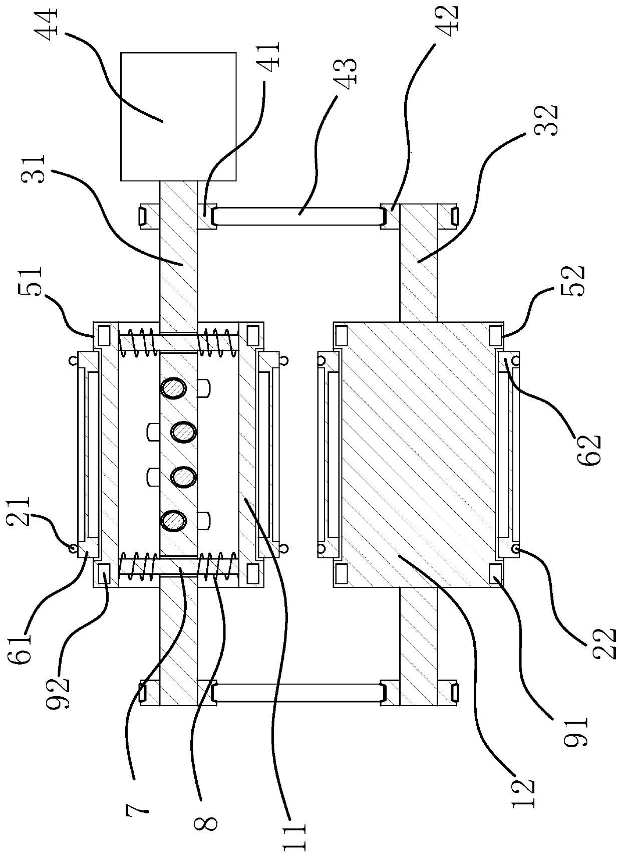
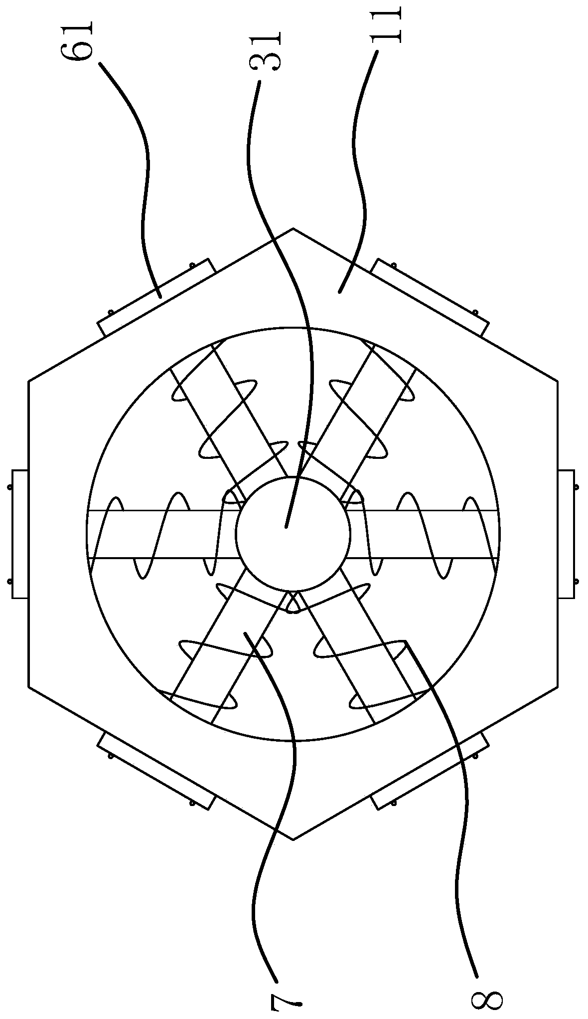
[0020] Such as figure 1 with figure 2 As shown, the switching device comprises a cylinder one 11 with a regular polygonal cross section and a cylinder two 12 of the same size as the cylinder one 11, each plane of the cylinder one 11 has a conductive terminal one 21 respectively, and each plane of the cylinder two 12 has a Conductive terminal 1 21 corresponds to conductive terminal 2 22 one by one, drum 11 is connected by rotating shaft 1 31, drum 2 12 is connected by rotating shaft 2 32, and the two ends of rotating shaft 1 31 are respectively fixedly provided with gear 1 41, and the two ends of rotating shaft 2 32 are fixed. The ends are respectively fixedly provided with gear two 42, gear one 41 and gear two 42 on the ...


PUM


Abstract

The invention provides a power switching device in a high voltage power distribution system. The power switching device comprises roller I having the cross section in a equilateral polygon shape and aroller II having the same dimension as the roller I. conductive terminals I are arranged on all planes of the roller I; conductive terminals II corresponding to the conductive terminals I are arranged on all planes of the roller II; and the roller I is connected by a rotating shaft I and the roller II is connected by a rotating shaft II. Gear wheels I are fixedly arranged at the two ends of the rotating shaft I; gear wheels II are fixedly arranged at the two ends of the rotating shaft II; the gear wheels I and the gear wheels II at the same sides of the gear wheels I are connected by synchronous toothed belts; and the rotating shaft I is connected with a stepping motor. A combined assembly that can drive the roller I and the roller II to make translation when the conductive terminals on the roller I and the conductive terminals on the roller II face each other directly is arranged between the roller I and the roller II. The power switching device has advantages of high safety and great convenience in operation and the like.

Description

technical field [0001] The invention relates to electric control equipment of a high-voltage power distribution system, in particular to a power switching device in the high-voltage power distribution system. Background technique [0002] In the high-voltage power distribution system, due to reasons such as high voltage and thick wires, there are many safety hazards in the switching of distribution power sources, such as arcs, electric sparks, magnetic fields, etc., which are not good for operating equipment and operators. [0003] The traditional knife-type switch, because the distance between the conductive terminals gradually decreases during the contact process, an arc is generated, causing damage to the conductive terminals, and there is a great safety hazard. The reason is that when the knife is closed, the included angle is gradually smaller. The change speed of the included angle corresponds to a relatively small reduction speed of the distance between the two conduc...

Claims


Application Information

Patent Timeline
Patent Type & Authority Patents(China)
IPC IPC(8): H01H3/26H01H3/28H01H3/32H01H3/40
CPCH01H3/26H01H3/28H01H3/32H01H3/40
Inventor 陈自球
Owner 山东光明电力科技有限公司
Features
  • R&D
  • Intellectual Property
  • Life Sciences
  • Materials
  • Tech Scout
  • Unparalleled Data Quality
  • Higher Quality Content
  • 60% Fewer Hallucinations
Learn More