
Differentiated QoS based multi-service hierarchical topology routing method and system

A layered topology and multi-service technology, applied in the field of communication, can solve problems such as network congestion and load imbalance, achieve the effect of reducing mutual influence, reducing local congestion, and meeting differentiated QoS requirements

Active Publication Date: 2018-06-15
BEIJING UNIV OF POSTS & TELECOMM +2
View PDF9 Cites 6 Cited by
  • Summary
  • Abstract
  • Description
  • Claims
  • Application Information

AI Technical Summary

Problems solved by technology

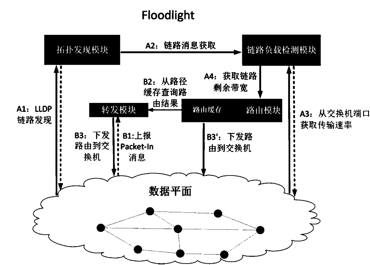
[0005] The present invention provides a multi-service hierarchical topology routing method and system based on differentiated QoS that overcomes the above problems or at least partially solves the above problems, and solves network congestion caused by multi-service traffic competition on the PON in the prior art and load imbalance

Method used


Image

  • Differentiated QoS based multi-service hierarchical topology routing method and system
  • Differentiated QoS based multi-service hierarchical topology routing method and system
  • Differentiated QoS based multi-service hierarchical topology routing method and system

Examples


Embodiment Construction

[0037] The specific implementation manners of the present invention will be further described in detail below in conjunction with the accompanying drawings and embodiments. The following examples are used to illustrate the present invention, but are not intended to limit the scope of the present invention.

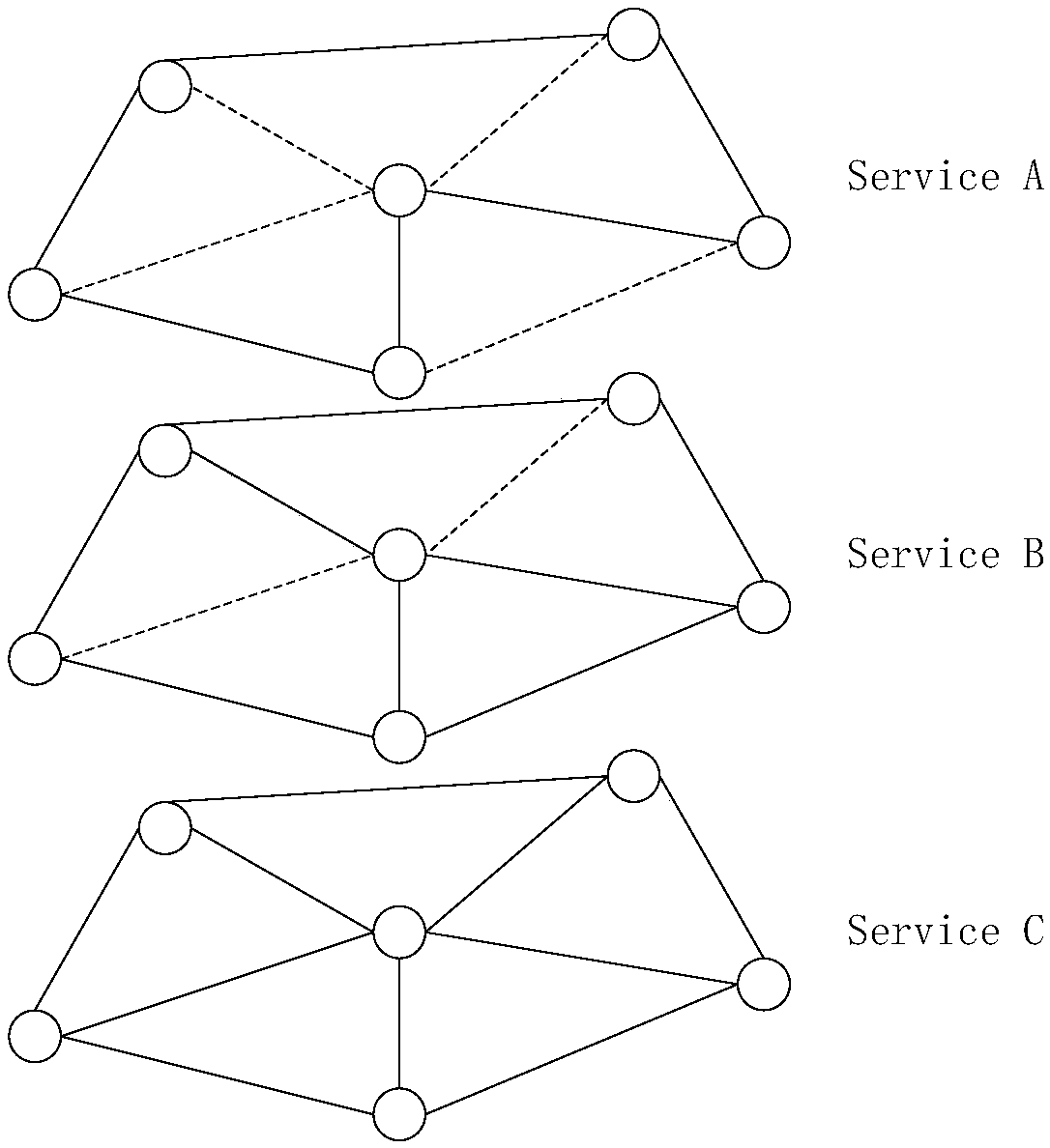
[0038] Such as figure 1 As shown, the figure shows a multi-service layered topology routing method, including:

[0039] S1. Based on the service quality QoS requirements of the service, calculate the bandwidth threshold of the link required by each service;

[0040] S2. According to the bandwidth threshold and the current network state, delete links in the network topology that do not meet the bandwidth threshold, generate a hierarchical topology of each service, and calculate the service cost of each service on the hierarchical topology shortest routing path.

[0041] In this embodiment, in the step S1, the QoS requirements of the service include delay requirements, pa...


PUM


Abstract

The invention provides a differentiated QoS based multi-service hierarchical topology routing method and system. The method includes the following steps: S1, based on the quality of service (QoS) requirements of services, calculating a link bandwidth threshold required for each type of service; and S2, according to the bandwidth threshold and the current network state, deleting links that do not satisfy the bandwidth threshold in the network topology, generating a hierarchical topology for each type of service, and calculating the shortest routing path of each type of service on the hierarchical topology. The corresponding logical hierarchical topology is generated for each type of service, the QoS requirements of the services and the load balancing of the network are comprehensively considered, the load balancing level of the network can be effectively improved, the interaction effect between service flows can be reduced, the network load balancing can be maximally optimized in the routing process of distinguishing the services, and thus each link can have the maximum residual bandwidth, the local congestion of the network can be reduced, and the interaction effect between the service flows can be reduced.

Description

technical field [0001] The present invention relates to the technical field of communication, and more specifically, to a multi-service layered topology routing method and system based on differentiated QoS. Background technique [0002] PON (Passive Optical Network, passive optical network) means that (in the optical distribution network) does not contain any electronic devices and electronic power supplies, and ODN (Optical Distribution Network, optical distribution network) is all composed of optical splitters (Splitter) and other wireless devices. source devices, without the need for expensive active electronics. A passive optical network includes an OLT (Optical Line Terminal, Optical Line Terminal) installed in a central control station, and a group of supporting ONUs (Optical Network Unit, Optical Network Unit) installed in user sites. The ODN between the OLT and the ONU includes optical fibers and passive optical splitters or couplers. [0003] PON is a widely used...

Claims


Application Information

Patent Timeline
IPC IPC(8): H04L12/725H04L12/803
CPCH04L45/302H04L47/125
Inventor 郭一珺李江舟葛维春罗涛郝建军杜瑜罗桓桓周桂平王英杰于波涛
Owner BEIJING UNIV OF POSTS & TELECOMM
Learn More