Automatic metal surface treatment device

A metal surface treatment and vertical plate technology, which is applied to grinding drive devices, metal processing equipment, grinding machines, etc., can solve the problems of unstable wire drawing strength, affecting the yield, and uneven wire flow, so as to ensure the quality of wire drawing and processing. quality, improved straightness

Active Publication Date: 2018-06-19
苏州丰川电子科技有限公司
View PDF5 Cites 3 Cited by
  • Summary
  • Abstract
  • Description
  • Claims
  • Application Information

AI Technical Summary

Problems solved by technology

At present, the traditional metal surface straight drawing adopts manual rotation of the rotating shaft, and the metal round tube is set on the rotating shaft. There is an abrasive belt frame above the rotating shaft, and a transmission wheel is installed on the abrasive belt frame. Setting, the abrasive belt is driven by the motor to rotate around the transmission wheel, and the bottom edge of the abrasive belt is manually pressed down with a wooden block and attached to the metal surface. With the linear motion of the bottom edge of the abrasive belt and the rotation of the rotating shaft, the metal tube is driven to rotate, and the metal tube is placed on the metal surface. Pull out the straight wire; obviously, the pressure of the above abrasive belt on the metal surface and the speed of the rotating shaft are random and uncontrollable, resulting in the inclination of the straight wire drawing on the metal surface, a large error in the straightness of the wire drawing, and instability of the wire drawing force. The uneven flow seriously affects the wire drawing quality of the metal surface, and the wire drawing efficiency is low; at the same time, the wire drawing defect causes the metal surface to have mottled phenomenon after oxidation treatment, which affects the yield and increases the production cost

Method used


Image

  • Automatic metal surface treatment device
  • Automatic metal surface treatment device
  • Automatic metal surface treatment device

Examples


Embodiment 1

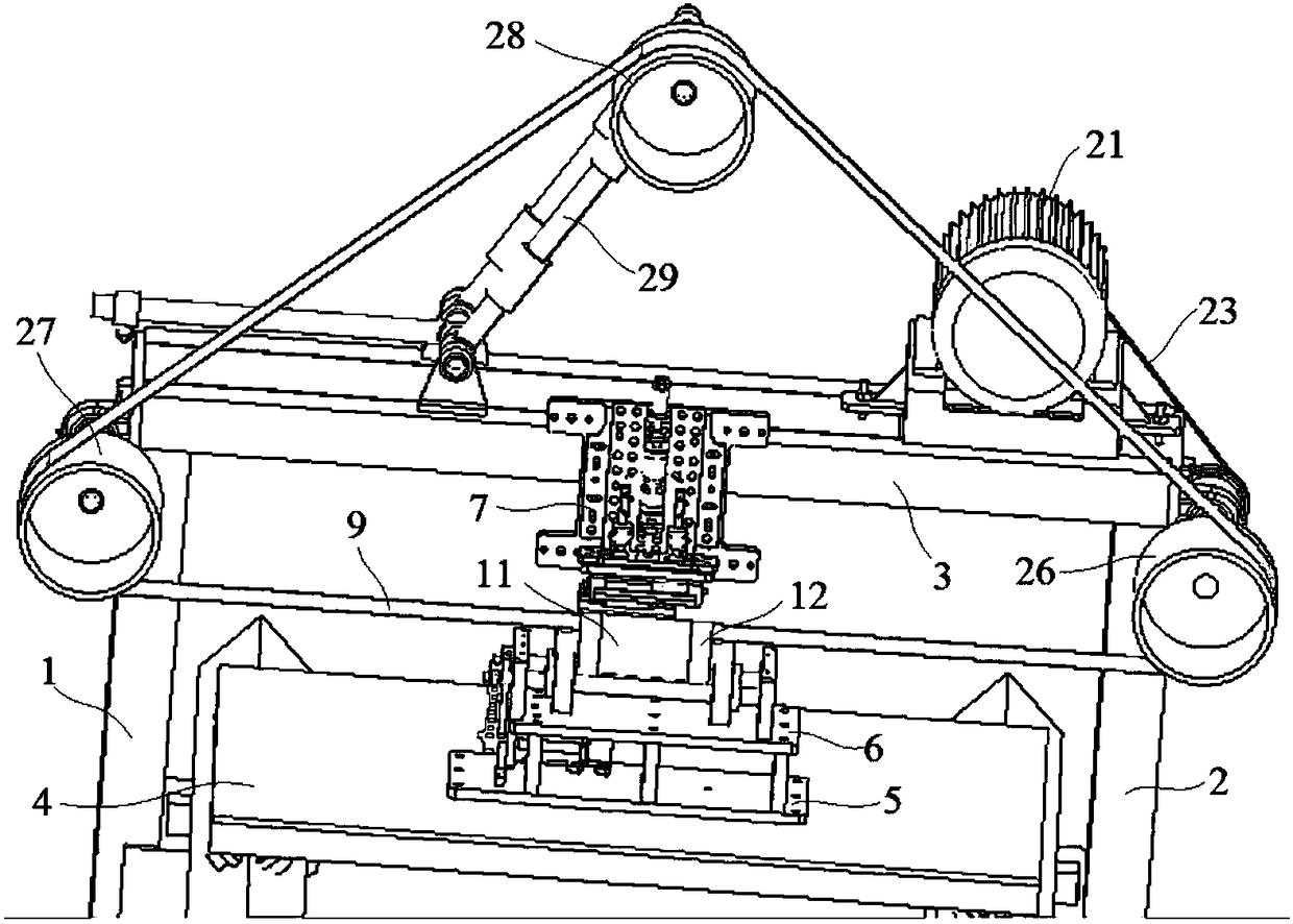
[0029] Embodiment 1: An automatic metal surface treatment device, including a left vertical plate 1, a right vertical plate 2, a beam plate 3, a carrier plate 4, a base plate 5, a clamp seat 6, a pressing mechanism 7 and an abrasive belt 9, the left The vertical plate 1 and the right vertical plate 2 are arranged in parallel, the beam plate 3 bridges the left vertical plate 1 and the right vertical plate 2, and the two ends of the lower surface of the beam plate 3 are respectively fixed to the upper surfaces of the left vertical plate 1 and the right vertical plate 2 connection, the two sides of the carrier plate 4 are installed and connected with the left vertical plate 1 and the right vertical plate 2 respectively, the base plate 5 is installed on the upper surface of the carrier plate 4, and the pressing mechanism 7 is installed on the front side of the beam plate 3, so The fixture seat 6 is installed above the base plate 5, the abrasive belt 9 is horizontally arranged direc...

Embodiment 2

[0035] Embodiment 2: An automatic metal surface treatment device, including a left vertical plate 1, a right vertical plate 2, a beam plate 3, a carrier plate 4, a base plate 5, a clamp seat 6, a pressing mechanism 7 and an abrasive belt 9, the left The vertical plate 1 and the right vertical plate 2 are arranged in parallel, the beam plate 3 bridges the left vertical plate 1 and the right vertical plate 2, and the two ends of the lower surface of the beam plate 3 are respectively fixed to the upper surfaces of the left vertical plate 1 and the right vertical plate 2 connection, the two sides of the carrier plate 4 are installed and connected with the left vertical plate 1 and the right vertical plate 2 respectively, the base plate 5 is installed on the upper surface of the carrier plate 4, and the pressing mechanism 7 is installed on the front side of the beam plate 3, so The fixture seat 6 is installed above the base plate 5, the abrasive belt 9 is horizontally arranged direc...


PUM


Abstract

The invention discloses an automatic metal surface treatment device which comprises a left vertical plate, a right vertical plate, a beam plate, a carrier plate, a base plate, a clamp base, a pressing-down mechanism and an abrasive belt. The left vertical plate and the right vertical plate are arranged in parallel. The beam plate is in bridging connection with the left vertical plate and the rightvertical plate. An output shaft of a motor is provided with a driving wheel, the driving wheel is in transmission connection with a driving auxiliary wheel through a belt, an air cylinder is vertically installed on the front surface of an installation plate, a piston rod of the air cylinder is fixedly connected with a pressing-down plate, a middle shaft is sleeved with a left fixing ring and a right fixing ring from the two ends of a supporting sleeve, the left fixing ring and the right fixing ring make close contact with the two end faces of the supporting sleeve correspondingly, and the supporting sleeve is sleeved with a circular pipe which is fixed through the left fixing ring and the right fixing ring. Straight wiredrawing operation of the metal surface can be automatically achieved,wiredrawing straightness, wire flow uniformity and wiredrawing efficiency are improved, the wiredrawing quality of the metal circular pipe is ensured, and the rate of finished products is improved.

Description

technical field [0001] The invention relates to an automatic metal surface treatment device, which belongs to the technical field of metal surface treatment. Background technique [0002] Straight wire drawing on the metal surface is the preprocessing of the surface of the part to meet the various needs of the product. When the metal surface is straight drawn, especially the aluminum alloy round tube, there are certain requirements for the straightness of the drawing and the uniformity of the wire flow, which reflects the drawing quality of the metal surface. At present, the traditional metal surface straight drawing adopts manual rotation of the rotating shaft, and the metal round tube is set on the rotating shaft. There is an abrasive belt frame above the rotating shaft, and a transmission wheel is installed on the abrasive belt frame. Setting, the abrasive belt is driven by the motor to rotate around the transmission wheel, and the bottom edge of the abrasive belt is man...

Claims


Application Information

Patent Timeline
Patent Type & Authority Applications(China)
IPC IPC(8): B24B21/02B24B21/00B24B21/20B24B21/18B24B41/06B24B47/00
CPCB24B21/006B24B21/02B24B21/18B24B21/20B24B41/067B24B47/00
Inventor 韦立强赵长亮蒋燕
Owner 苏州丰川电子科技有限公司
Why Eureka
Try Eureka