Rotary powder box for steel wire production

A technology of powder box and steel wire, applied in the field of rotating powder box for steel wire production, can solve the problems of uneven surface contamination of steel wire, affecting the tensile performance of steel wire, scratching the surface of steel wire, etc. The effect of increasing the chance of contact

Pending Publication Date: 2020-06-30
河南巨力钢丝绳制造有限公司
View PDF0 Cites 0 Cited by
  • Summary
  • Abstract
  • Description
  • Claims
  • Application Information

AI Technical Summary

Problems solved by technology

[0002] In the production process of steel wire rope, it is necessary to draw thicker steel wire into thinner steel wire, and then carry out twisting and closing. In the drawing process, in order to ensure the drawing quality, it is necessary to apply drawing powder on the surface of the steel wire before drawing , the traditional operation method is to make the steel wire pass through the box that stores the wire drawing powder, so that the surface of the steel wire is covered with the wire drawing powder. Because the particle size of the wire drawing powder is small, and it is stored in the storage box for a long time, it will The problem of hardening occurs, resulting in uneven contamination on the surface of the steel wire, resulting in insufficient lubrication when the steel wire passes through the drawing die, scratching the surface of the steel wire, and affecting the tensile properties of the steel wire

Method used


Image

  • Rotary powder box for steel wire production
  • Rotary powder box for steel wire production
  • Rotary powder box for steel wire production

Examples


Embodiment approach 1

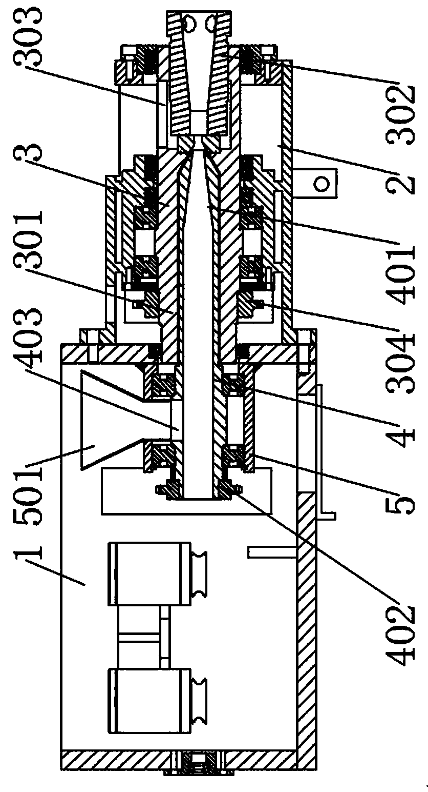
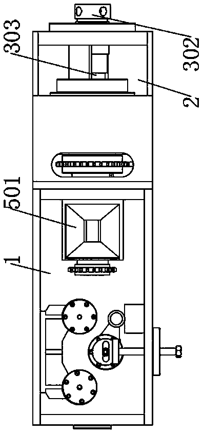
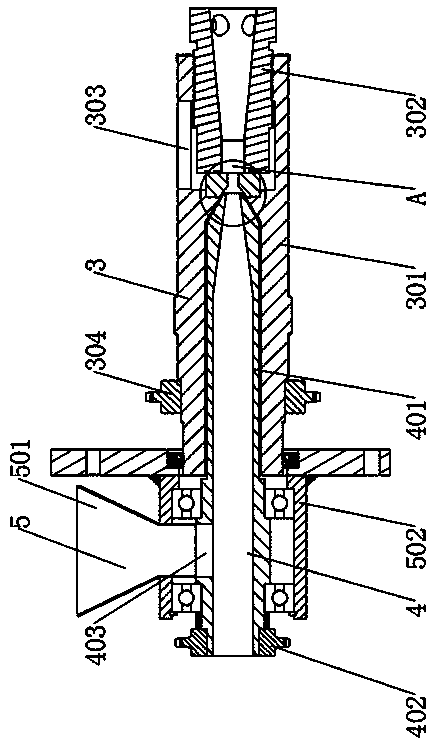
[0026] see Figure 1-5 , the present invention provides a technical solution: a rotary powder box for steel wire production, including a powder box 1 and a water box 2 that are independent of each other and fixedly installed. 3. It includes the first rotating body 301 which is hollow inside and open at both ends. The inside of the first rotating body 301 is coaxially fixed with a drawing die, and the inside of the powder box 1 is horizontally rotated to install a powder storage mechanism 4. And the second rotating body 401 with both ends open, the second rotating body 401 is partially coaxially nested and installed inside the first rotating body 301, the first rotating body 301 and the second rotating body 401 can rotate relatively, the second rotating body 401 is located on the outer peripheral wall of the first rotating body 301 to provide a powder inlet 403 , and the powder inlet 403 communicates with the hollow area inside the second rotating body 401 .

[0027] The insid...

Embodiment approach 2

[0039] see Figure 6-7 , the present invention provides a technical solution: a rotary powder box for steel wire production, including a powder box 1 and a water box 2 that are independent of each other and fixedly installed. 3. It includes the first rotating body 301 which is hollow inside and open at both ends. The inside of the first rotating body 301 is coaxially fixed with a drawing die, and the inside of the powder box 1 is horizontally rotated to install a powder storage mechanism 4. And the second rotating body 401 with both ends open, the second rotating body 401 is partially coaxially nested and installed inside the first rotating body 301, the first rotating body 301 and the second rotating body 401 can rotate relatively, the second rotating body 401 is located on the outer peripheral wall of the first rotating body 301 to provide a powder inlet 403 , and the powder inlet 403 communicates with the hollow area inside the second rotating body 401 .

[0040] The insid...


PUM


Abstract

The invention discloses a rotary powder box for steel wire production. The rotary powder box comprises a powder box and a water box which are independent of each other and are fixedly mounted. A moldcore fixing mechanism is horizontally and rotationally mounted in the water box and comprises a first rotary body, wherein the interior of the first rotary body is hollow, and openings are formed in the two ends of the first rotary body. A wire drawing mold is coaxially and fixedly mounted in the first rotary body. A powder storage mechanism is horizontally and rotationally mounted in the powder box and comprises a second rotary body, wherein the interior of the second rotary body is hollow, and openings are formed in the two ends of the second rotary body. The second rotary body is partiallyand coaxially embedded and mounted in the first rotary body. The first rotary body and the second rotary body can rotate relatively. By means of the rotary powder box for steel wire production, the powder storage mechanism is rotated, so that inside powder constantly rolls, powder caking is avoided, powder has two motion modes of axial pulling and rotating relative steel wires, it is guaranteed that the surfaces of the steel wires are stained with powder evenly, and drawing quality is guaranteed.

Description

technical field [0001] The invention relates to the technical field of steel wire rope production equipment, in particular to a rotary powder box for steel wire production. Background technique [0002] In the production process of steel wire rope, it is necessary to draw thicker steel wire into thinner steel wire, and then carry out twisting and closing. In the drawing process, in order to ensure the drawing quality, it is necessary to apply drawing powder on the surface of the steel wire before drawing , the traditional operation method is to make the steel wire pass through the box that stores the wire drawing powder, so that the surface of the steel wire is covered with the wire drawing powder. Because the particle size of the wire drawing powder is small, and it is stored in the storage box for a long time, it will The problem of hardening occurs, resulting in uneven contamination on the surface of the steel wire, resulting in insufficient lubrication when the steel wir...

Claims


Application Information

Patent Timeline
Patent Type & Authority Applications(China)
IPC IPC(8): B21C9/00
CPCB21C9/00
Inventor 施聪夏利科刘国庆
Owner 河南巨力钢丝绳制造有限公司
Why Eureka
Try Eureka