Crankshaft labelling device

A crankshaft, vertically placed technology, applied in the field of crankshaft processing, can solve the problems of low paste efficiency, difficult separation of the adhesive layer and the paper layer, etc.

Active Publication Date: 2018-06-19
CHONGQING HONGLEI MACHINERY MFG
View PDF4 Cites 2 Cited by
  • Summary
  • Abstract
  • Description
  • Claims
  • Application Information

AI Technical Summary

Problems solved by technology

But most of the pasting methods are manual pasting, the adhesive layer and

Method used


Image

  • Crankshaft labelling device
  • Crankshaft labelling device

Examples


Embodiment Construction

[0014] The following is further described in detail through specific implementation methods:

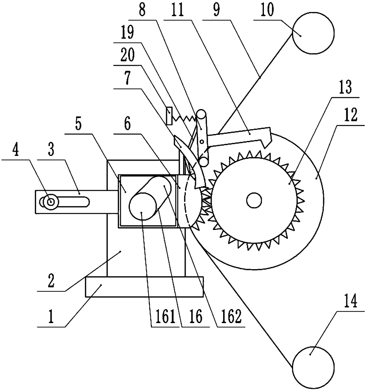
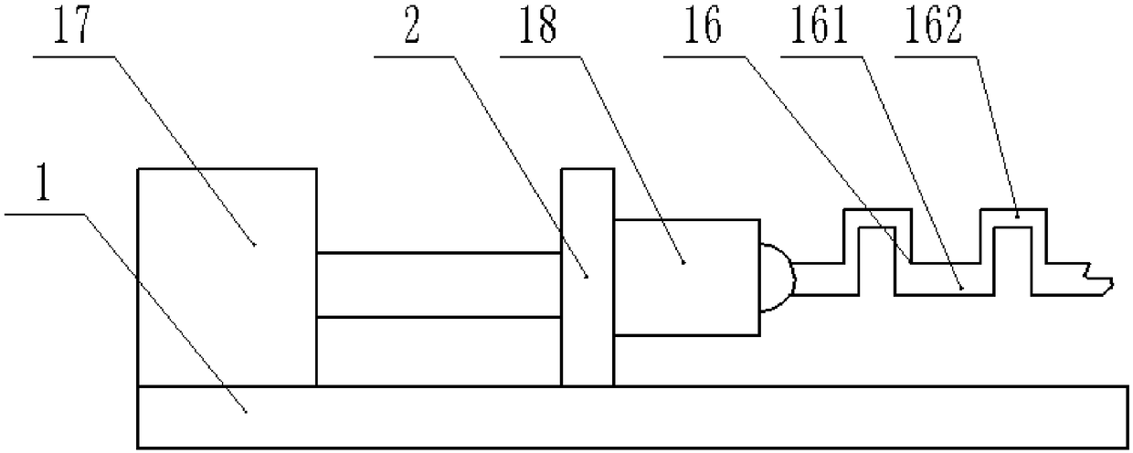
[0015] The reference signs in the drawings of the description include: slide rail 1, slide plate 2, connecting piece 3, screw 4, through hole 5, swing plate 6, arc rod 7, vertical rod 8, double-sided adhesive tape 9, discharge roller 10 , Clamping rod 11, rolling disc 12, gear 13, receiving roller 14, crankshaft 16, main journal 161, connecting rod journal 162, cylinder 17, motor 18, blade 19, baffle plate 20.

[0016] The embodiment is basically as attached Figure 1-Figure 2 Shown: A crankshaft labeling device, including a frame, such as figure 2 As shown, the frame is provided with a horizontal slide rail 1, and the slide rail 1 is slidably connected with a vertically placed slide plate 2. The right side of the slide plate 2 is welded with a motor 18 connected to the crankshaft 16, and the motor 18 is provided with a heat sink. Sheet, the left end of slide rail 1 is provided wi...


PUM


Abstract

The invention relates to a crankshaft labelling device, which comprises a rack. A motor is arranged on the rack; a vertically placed oscillating plate is arranged on the rack; a through hole is formedin the middle of the oscillating plate; two opposite side parts of the oscillating plate are provided with pulling teeth and a connecting plate; the connecting plate is movably connected onto the rack; a gear meshed with the pulling teeth is rotatably connected onto the rack; a grinding plate is connected onto the gear; a clamping rod is arranged above the gear; a clamping block and a vertical rod clamped on the gear are arranged on the two ends of the clamping rod; the middle part of the vertical rod is rotatably connected onto the rack; an arc-shaped blade is arranged on the top part of thevertical rod; an elastic piece is arranged between the rack and the top end of the vertical rod; an arc-shaped rod pressing against the bottom end of the vertical rod is arranged on the oscillating plate; a discharging roller is arranged above the grinding plate; a winding roller is arranged below the grinding plate; a double-faced adhesive reel is arranged on the discharging roller; a double-faced adhesive tape winds on the double-faced adhesive reel; and one end, far away from the double-faced adhesive reel, of the double-faced adhesive tape extends onto the winding roller. According to thescheme, the double-faced adhesive tape is automatically adhered onto a crankshaft.

Description

technical field [0001] The invention relates to the technical field of crankshaft processing, in particular to a crankshaft labeling device. Background technique [0002] The crankshaft is the main rotating part of the engine. After the connecting rod is installed, it can undertake the up and down reciprocating motion of the connecting rod and turn it into a circular motion. The crankshaft mainly includes a main journal and a connecting rod journal, and the connecting rod journal is located on the outside of the main journal. During the production and processing of the crankshaft, some labels are often attached to the crankshaft to mark it for workers to distinguish. Most of the current labels use double-sided tape. The double-sided tape used to mark the crankshaft is usually provided with an adhesive layer and a paper layer. The adhesive layer is attached to the paper layer, and the adhesive layer is attached to the paper layer. It has characters and other marks. When in ...

Claims


Application Information

Patent Timeline
IPC IPC(8): B65C9/04B65C9/36B65C9/18B65C3/02
CPCB65C3/02B65C9/04B65C9/1803B65C9/36
Inventor 陈协夫
Owner CHONGQING HONGLEI MACHINERY MFG
Why Eureka
Try Eureka