A steerable trolley line system

A trolley line and contact technology, applied in the field of steerable trolley line system, can solve the problems of easy wear and tear, and achieve the effect of simple operation and easy maintenance

Inactive Publication Date: 2020-11-03
CHENGDU TECH UNIV
View PDF5 Cites 0 Cited by
  • Summary
  • Abstract
  • Description
  • Claims
  • Application Information

AI Technical Summary

Problems solved by technology

In this system, since the brush and the conductor must be kept in close contact, it is easy to wear and tear, which is a consumable
[0003] Also, current current collectors are limited to back and forth motion in the same direction

Method used


Image

  • A steerable trolley line system
  • A steerable trolley line system
  • A steerable trolley line system

Examples


Embodiment Construction

[0023] Below in conjunction with accompanying drawing, the present invention is described in detail.

[0024] In order to make the object, technical solution and advantages of the present invention clearer, the technology of the present invention will be further described in detail below in conjunction with the accompanying drawings and embodiments. It should be understood that the specific embodiments described here are only used to explain the present invention, not to limit the present invention.

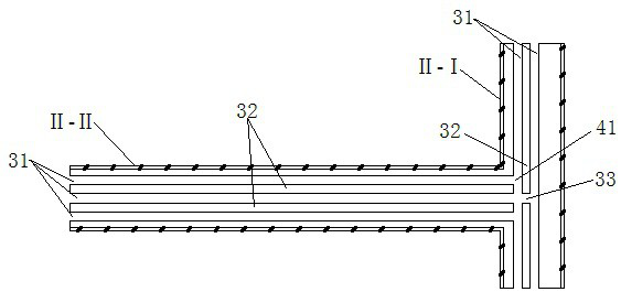
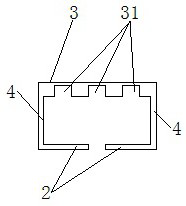
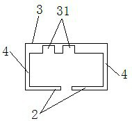
[0025] As shown in the figure, the steerable trolley line system includes collector I and conductor rail system II, and the three-phase circuit of collector I is respectively connected to the first contact, the second contact, the third contact, and the top plate 11 , the bottom plate 12 and the middle mounting block 13, the middle mounting block 13 respectively fixes the top plate 11 and the bottom plate 12 up and down, the contacts are installed on the top plate 1112, and the b...


PUM


Abstract

The invention discloses a novel steerable sliding line system comprising a current collector and two conductive rails, wherein the three-phase circuit of the current collector is connected with a positive contact, a negative contact, a ground contact, a top plate, a bottom plate and an intermediate mounting block. The top plate and the bottom plate are fixed to the upper and lower sides of the intermediate mounting block respectively. The contacts are all mounted on the top plate and / or the bottom plate. The two conductive rails are perpendicular to each other. Each of the conductive rails includes a three-phase circuit slide rail which comes into continuous contact with the positive contact, the negative contact and the ground contact of the moving current collector correspondingly. Whenthe current collector is switched between the two conductive rails, the three-phase circuit of the current collector can be freely switched between the three-phase circuit slide rails of the two conductive rails.

Description

technical field [0001] The invention belongs to a steerable trolley line system in the field of electromechanical control, and in particular relates to a steerable trolley line system. Background technique [0002] Since the mobile device needs to constantly change positions, in each different position, the mobile device needs to be able to obtain power at any time, otherwise it cannot continue to move. At this time, the steerable trolley line system came into being. Several conductors are laid in parallel along the running track of the mobile equipment, and the power supply is connected. On the mobile equipment, a current collector that can take electricity from the conductor is installed. In this way, when the equipment moves, the collector operates synchronously with the equipment, and obtains power from the conductor at any time through the sliding contact between the brush and the conductor, and provides it to the equipment so that the equipment can continue to move. ...

Claims


Application Information

Patent Timeline
Patent Type & Authority Patents(China)
IPC IPC(8): H01R41/00
CPCH01R41/00
Inventor 朱成华朱芮璋付闫伦
Owner CHENGDU TECH UNIV
Why Eureka
Try Eureka