guide wire

A technology of a guide wire and a curved part is applied in the field of guide wires inserted into blood vessels, which can solve the problems of the guide wire hanging and the inability to reach the target site smoothly.

Active Publication Date: 2015-11-04
ASAHI INTECC CO LTD
View PDF9 Cites 0 Cited by
  • Summary
  • Abstract
  • Description
  • Claims
  • Application Information

AI Technical Summary

Problems solved by technology

Therefore, there is a problem that the front end of the guide wire is caught by the side branches of the peripheral blood vessels and cannot reach the target site smoothly.

Method used


Image

  • guide wire
  • guide wire
  • guide wire

Examples


Embodiment Construction

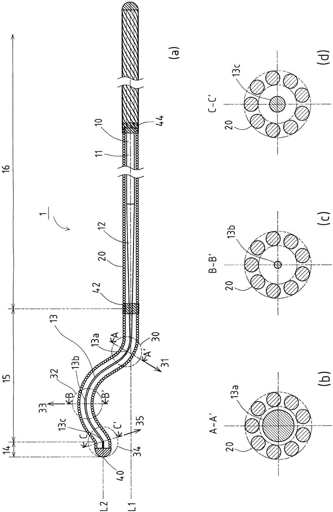
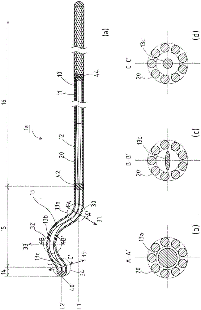
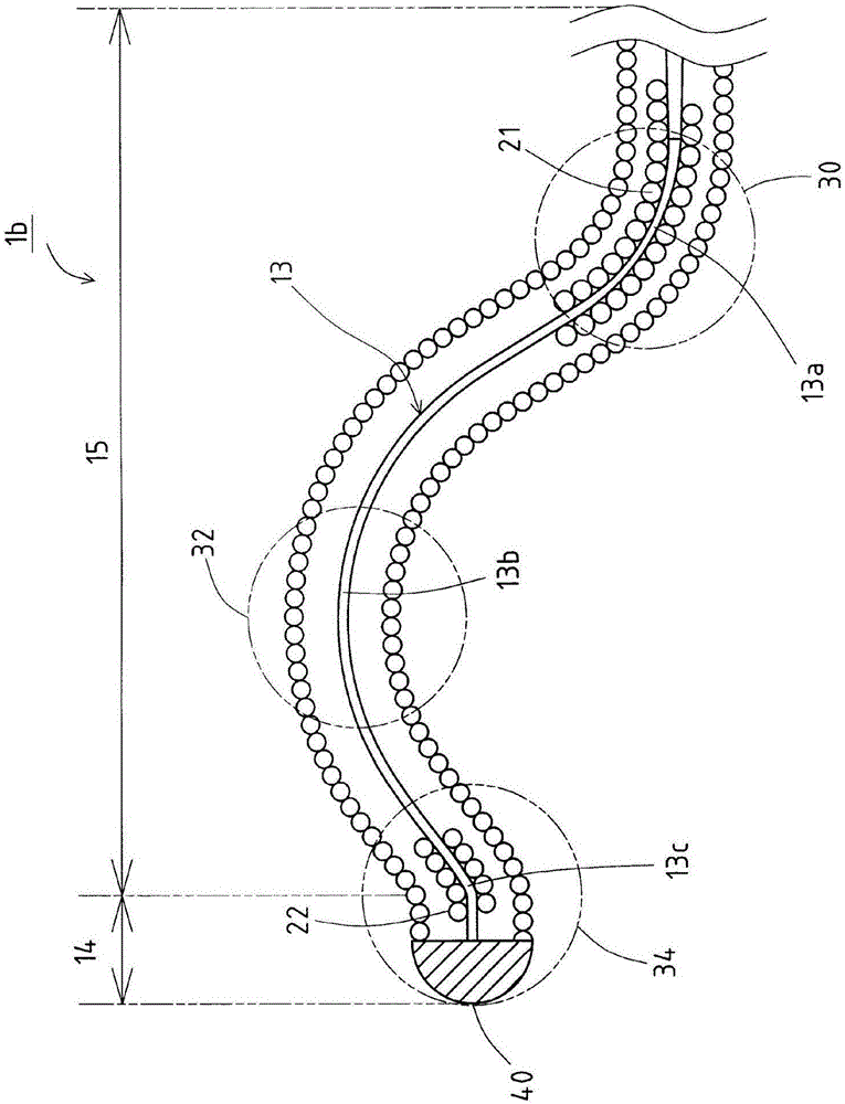
[0028] refer to figure 1 (a)~ Figure 5 (c) is described by taking the case where the guide wire 1 of this embodiment is used as an example. exist figure 1 (a)~ Figure 5 In (c), the left side of the illustration is the front end side (distal side) inserted into the body, and the right side is the rear end side (proximal side, proximal side) operated by technicians such as doctors. In addition, in each figure, the parts smaller than other parts such as the mandrel 10, the coil body 20, the bending parts 30, 32, and 34 shown below are slightly exaggerated according to the dimensional relationship with other parts for easy understanding. icon. In addition, for ease of understanding, the axial direction (longitudinal direction) of the guide wire 1 is shortened, and the overall and schematic illustration is shown, so the overall dimension is different from the actual one.

[0029] figure 1 The guide wire 1 shown in (a) is mainly composed of a mandrel 10 , a coil body 20 cov...


PUM


Abstract

In a guidewire (1), a second curved portion (32) has a higher flexibility than a first curved portion (30) and a third curved portion (34). Thus, a portion around the second curved portion (32) can bend to a large degree. Consequently, a distal tip (14) of the guidewire (1), in a state of being stuck on a side branch, can be released from the side branch and a distal region (15) can be prevented from being rotated around the second curved portion (32).

Description

technical field [0001] The present invention relates to guide wires for insertion into blood vessels. Background technique [0002] A guide wire is known as one of medical devices used in endovascular treatment such as percutaneous coronary angioplasty. A guide wire is a medical device used to guide a catheter, a stent, etc. to a target site in a blood vessel. [0003] In the past, as a method of inserting a guide wire into a blood vessel, puncture from the diameter of the mouse to the femoral artery (TFI) was the mainstream, and by promoting the miniaturization of medical devices, in recent years, it has become possible to reduce the burden on patients. Intrabrachial puncture (TBI) and radial artery puncture (TRI) from the wrist. [0004] Peripheral blood vessels such as the upper brachial artery and the radial artery are thinner, and there are many branches of the main branch and side branch. Therefore, there is a problem that the leading end of the guide wire is caught...

Claims


Application Information

Patent Timeline
Patent Type & Authority Patents(China)
IPC IPC(8): A61M25/09A61F2/95
CPCA61M25/09A61M2025/09083A61M2025/09175
Inventor 小杉知辉
Owner ASAHI INTECC CO LTD
Why Eureka
Try Eureka