Audio test method and audio test system

An audio test and audio technology, which is applied in branch equipment, electrical components, telephone communication, etc., can solve the problems of poor terminal stability and low reliability of audio test methods, and achieve the effect of improving reliability and stability.

Inactive Publication Date: 2018-06-19
SHANGHAI TRANSSION CO LTD
View PDF6 Cites 16 Cited by
  • Summary
  • Abstract
  • Description
  • Claims
  • Application Information

AI Technical Summary

Problems solved by technology

[0003] However, the current terminal only controls the acoustic performance of the electro-acoustic device in the early stage of research and development, but in the end, when the termina

Method used


Image

  • Audio test method and audio test system
  • Audio test method and audio test system
  • Audio test method and audio test system

Examples


no. 1 example

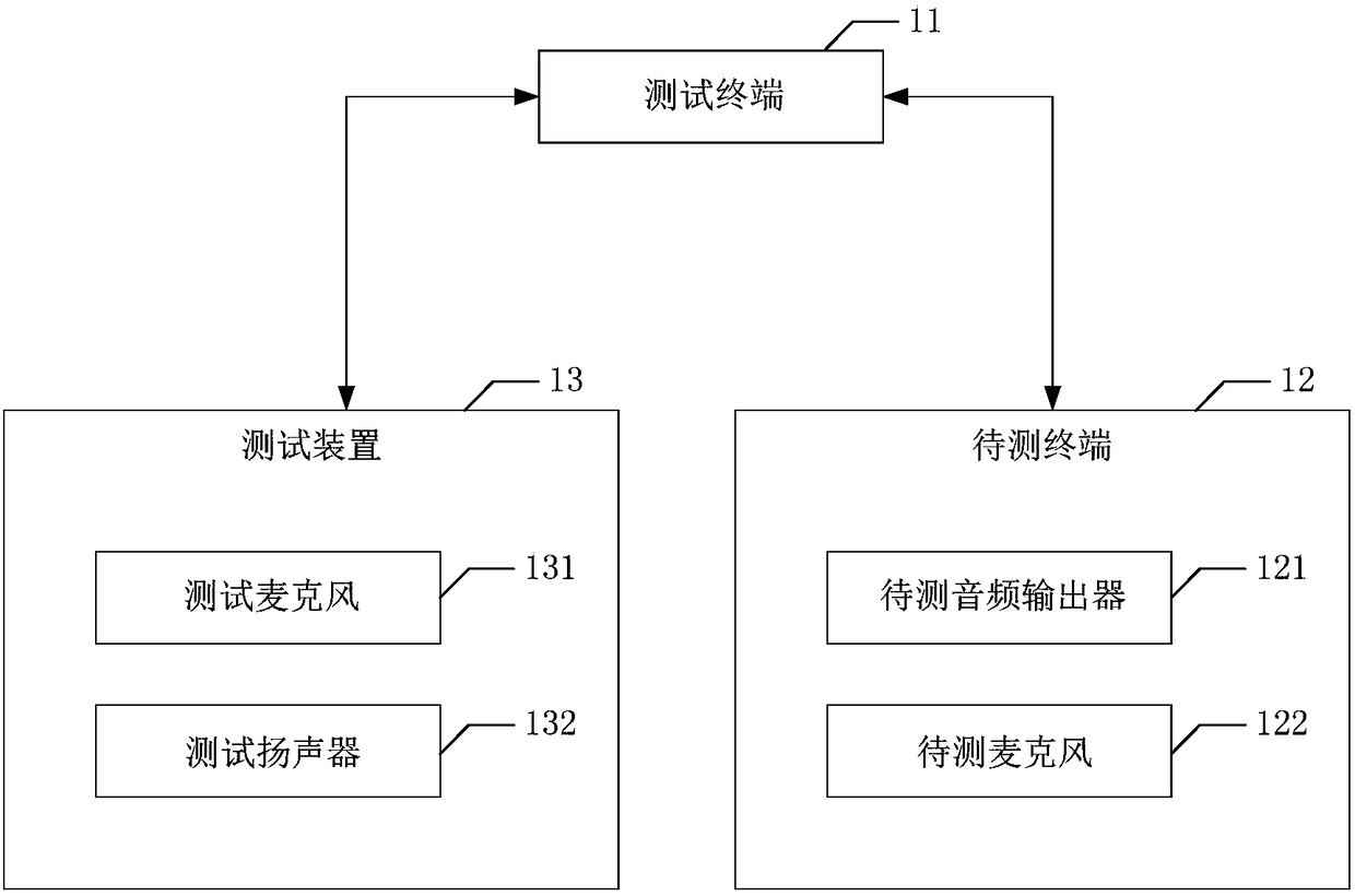
[0024] figure 1 It is a schematic structural diagram of the audio test system according to the first embodiment of the present invention. Such as figure 1 As shown, the audio test system includes a test terminal 11, a terminal to be tested 12, a test device 13, and a sealed box (not shown in the figure).

[0025] Wherein, the sealed box is used for placing the terminal under test 12 and the test device 13 , and the test terminal 11 is used for sending the first test signal to the terminal under test 12 .

[0026] In one embodiment, the test terminal 11 may be, but not limited to, an electronic device such as a computer that has the functions of sending and receiving electrical signals and comparing functions. The test terminal 11 sends a first test signal to the terminal under test 12 through a wired connection such as a data line connection.

[0027] Wherein, the terminal under test 12 includes an audio output device under test 121, and the audio output device 121 under te...

no. 2 example

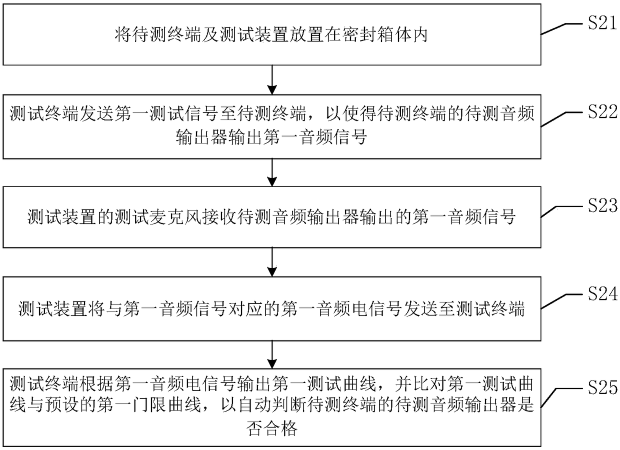
[0041] figure 2 It is a schematic flowchart of the audio testing method according to the second embodiment of the present invention. Please also refer to figure 1 and figure 2 , audio test methods include:

[0042] Step S21: placing the terminal to be tested 12 and the testing device 13 in a sealed box;

[0043] Wherein, the testing device 13 includes a testing microphone 131 , and the terminal under test 12 includes an audio output device under test 121 . In one embodiment, the test microphone 131 and / or the audio output device 121 to be tested are located in the sealed box.

[0044] Step S22: the test terminal 11 sends the first test signal to the terminal under test 12, so that the audio output device 121 under test of the terminal under test 12 outputs the first audio signal;

[0045] Step S23: the test microphone 131 of the test device 13 receives the first audio signal output by the audio output device 121 to be tested;

[0046] Step S24: the testing device 13 send...

no. 3 example

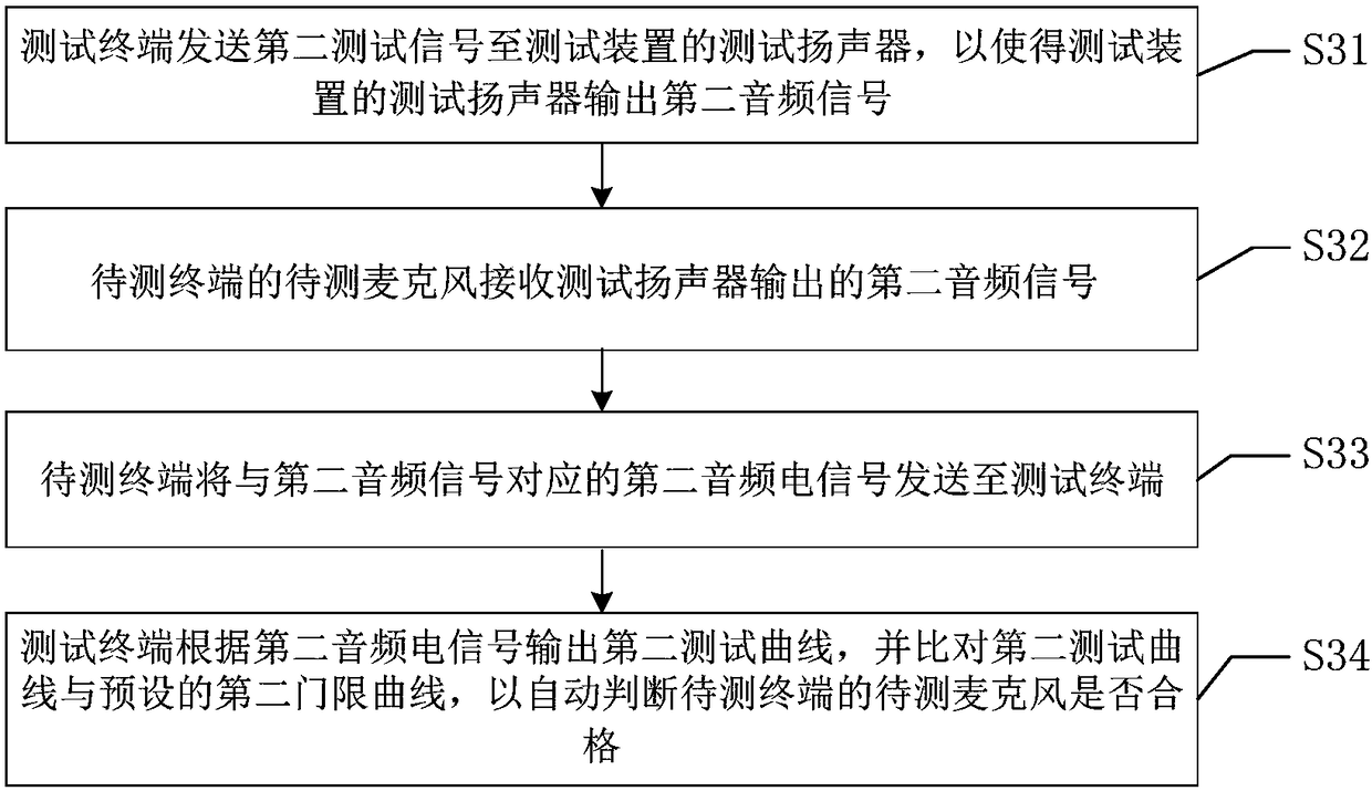
[0050] image 3 It is a schematic flowchart of the audio testing method according to the third embodiment of the present invention. Please also refer to figure 2 and image 3 , audio test methods include:

[0051] Step S31: the test terminal 11 sends a second test signal to the test speaker 132 of the test device 13, so that the test speaker 132 of the test device 13 outputs a second audio signal;

[0052] Step S32: the microphone 122 under test of the terminal under test 12 receives the second audio signal output by the test speaker 132;

[0053] Step S33: the terminal under test 12 sends the second electrical audio signal corresponding to the second audio signal to the testing terminal 11;

[0054] Step S34: The test terminal 11 outputs a second test curve according to the second audio electrical signal, and compares the second test curve with the preset second threshold curve to automatically determine whether the test microphone 122 of the test terminal 12 is qualifie...


PUM


Abstract

The invention relates to an audio test method, the method comprises the following steps: a to-be-tested terminal and a test device are placed in a sealed box; the test terminal sends a first test signal to the to-be-tested terminal so as to enable a to-be-tested audio output device of the to-be-tested terminal to output a first audio signal; the test device sends a first audio electric signal corresponding to the first audio signal to the test terminal; the test terminal outputs a first test curve according to the first audio electric signal and compares the first test curve with a preset first threshold curve so as to automatically judge whether the to-be-tested audio output device of the to-be-tested terminal is qualified. The invention also provides an audio test system. The audio testmethod and the audio test system provided by the invention directly perform audio test for the to-be-tested terminal and separately test the to-be-tested audio output device and a to-be-tested microphone of the to-be-tested terminal. Thus, reliability of test can be improved further, and stability of the to-be-tested terminal can be improved.

Description

technical field [0001] The invention relates to the technical field of audio testing, in particular to an audio testing method and an audio testing system. Background technique [0002] Nowadays, a terminal such as a mobile phone has become a necessity in people's daily life. The terminal is generally equipped with electro-acoustic devices such as speakers, receivers, and microphones. During the large-scale production process of the terminal, in order to ensure the audio performance of these devices, audio tests will be performed on the electro-acoustic devices. [0003] However, the current terminal only controls the acoustic performance of the electro-acoustic device in the early stage of research and development, but in the end, when the terminal is made into a finished product, there may still be defective products. Therefore, the current terminal audio test method is not reliable and easy Resulting in poor stability of the terminal. Contents of the invention [0004...

Claims


Application Information

Patent Timeline
IPC IPC(8): H04R29/00H04M1/24
Inventor 曹军张玉磊王成永
Owner SHANGHAI TRANSSION CO LTD
Why Eureka
Try Eureka