
Pressure casting mould and pressure casting device

A technology of die-casting mold and die-casting machine, which is applied in the field of mold forming, can solve the problems of easy wear, short service life of sprue sleeve, stuck injection head, etc.

Pending Publication Date: 2018-06-22
JIANGSU HAIJIN METALLIC GLASS TECH CO LTD
View PDF0 Cites 1 Cited by
  • Summary
  • Abstract
  • Description
  • Claims
  • Application Information

AI Technical Summary

Problems solved by technology

[0005] The object of the present invention is to provide a die-casting mold and a die-casting device to solve the problems in the prior art that the sprue sleeve is easily worn and strained when the material handle is pulled out from the die-casting mould, the sprue sleeve has a short service life, and it is easy to cause The technical problem of the injection head stuck in the sprue sleeve during the die-casting process

Method used

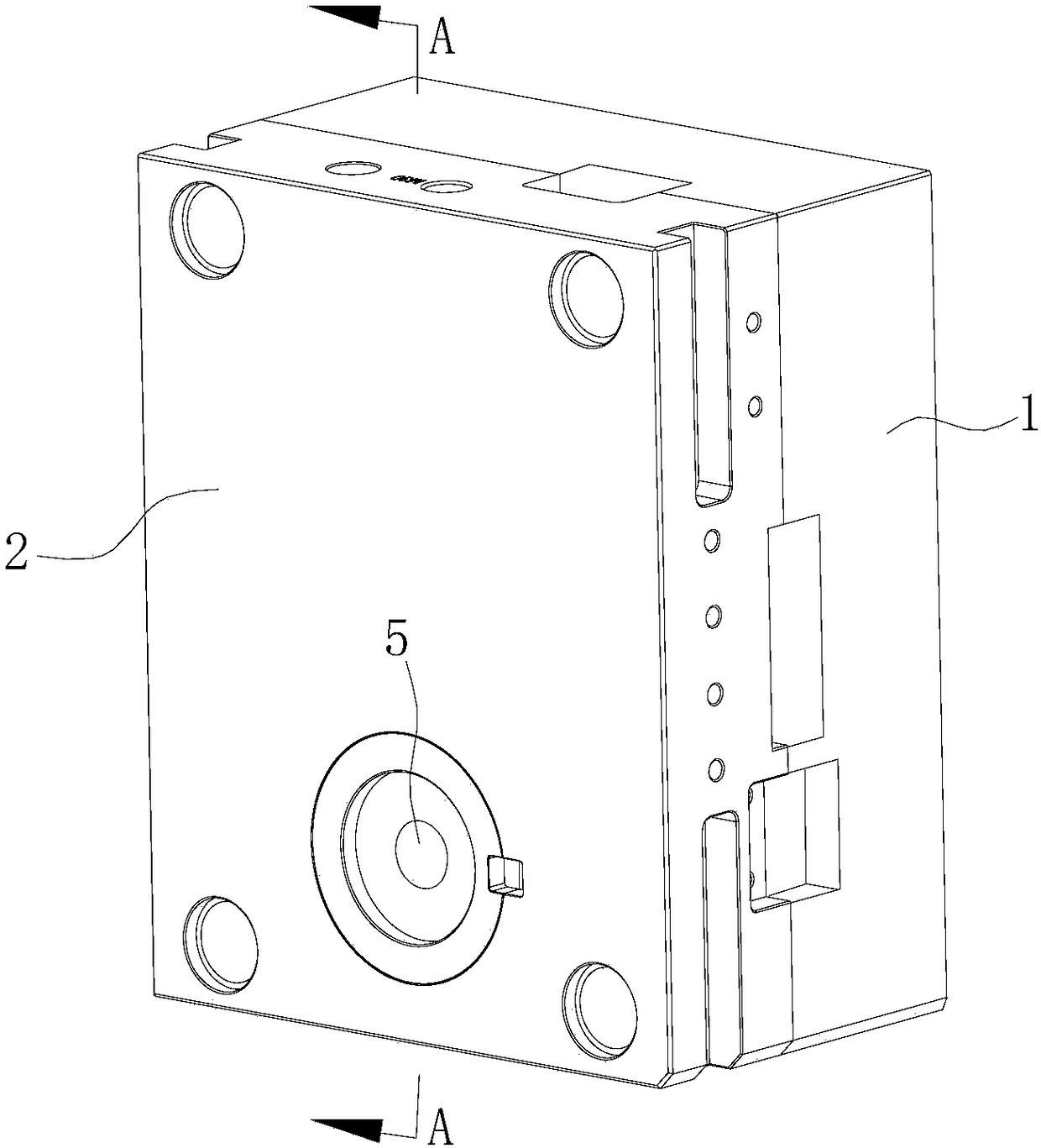
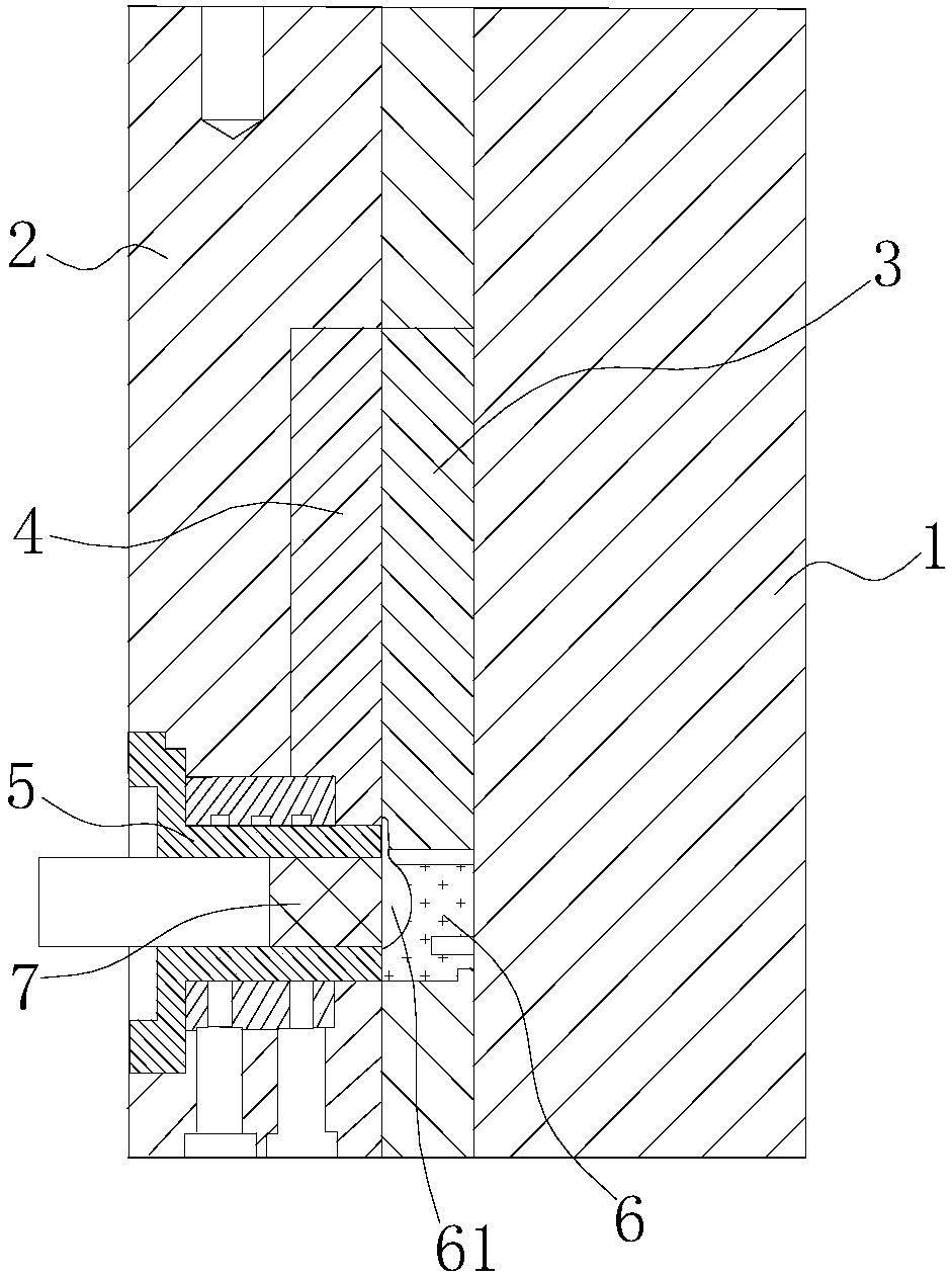
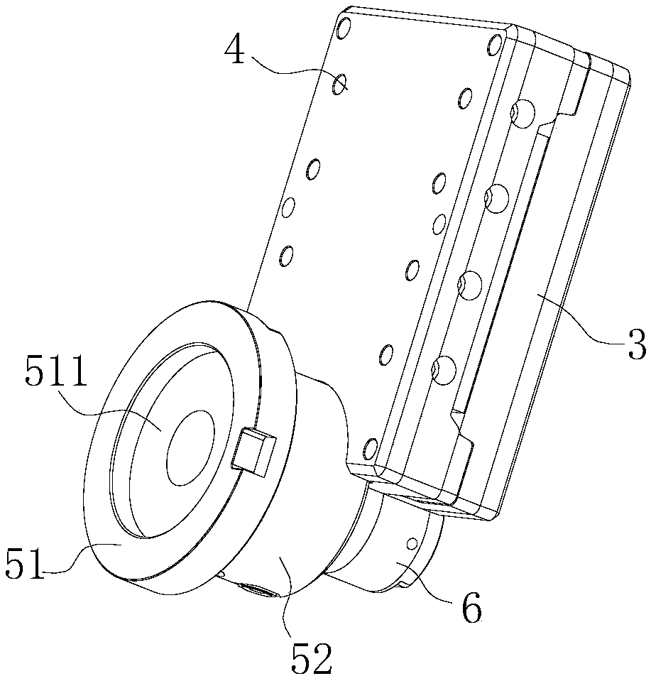

Image

  • Pressure casting mould and pressure casting device
  • Pressure casting mould and pressure casting device
  • Pressure casting mould and pressure casting device

Examples


Embodiment Construction

[0026] The technical solutions of the present invention will be clearly and completely described below in conjunction with the accompanying drawings. Apparently, the described embodiments are some of the embodiments of the present invention, rather than all of them. Based on the embodiments of the present invention, all other embodiments obtained by persons of ordinary skill in the art without making creative efforts belong to the protection scope of the present invention.

[0027] In the description of the present invention, it should be noted that the terms "center", "upper", "lower", "left", "right", "vertical", "horizontal", "inner", "outer" etc. The orientation or positional relationship indicated is based on the orientation or positional relationship shown in the drawings, and is only for the convenience of describing the present invention and simplifying the description, rather than indicating or implying that the device or element referred to must have a specific orient...


PUM


Abstract

The invention provides a pressure casting mould and a pressure casting device, and relates to the technical field of moulding. The pressure casting mould comprises a male mould plate and a female mould plate which are matched with each other; a moving mould core is arranged on the male mould plate; a fixed mould core is arranged on the female mould plate; when the male mould plate and the female mould plate are closed, the moving mould core and the fixed mould core form a mould cavity; a sprue bush is arranged on the female mould plate; a spure spreader is arranged on the male mould plate; a groove and a flow distributing channel which communicate with each other are formed in the spure spreader; when the male mould plate and the female mould plate are closed, the spure spreader is positioned out of the sprue bush; the groove of the spure spreader communicates with a pressure injection flow channel; the flow distributing channel of the spure spreader communicates with the mould cavity;the pressure casting device comprises a pressure casting machine and the pressure casting mould; a pressure injection head of the pressure casting machine is inserted into the sprue bush in a matchedmanner; and the stroke of the pressure injection head in the pressure injection flow channel is not less than the length of the pressure injection flow channel. According to the pressure casting mould and the pressure casting device, the sprue bush is not affected by the formation and separation of a material handle; the situations of sprue bush damages caused by tearing are reduced; the servicelife of the sprue bush is long; and the situations that the pressure injection head is clamped in the sprue bush are also reduced.

Description

technical field [0001] The invention relates to the technical field of mold forming, in particular to a die-casting mold and a die-casting device. Background technique [0002] In the field of casting processing, die casting is a precision casting method that uses high pressure to press molten metal into the mold cavity to form castings of various shapes. Among them, the mold is usually made of an alloy with a higher melting point. [0003] Existing die-casting molds generally include a sprue bushing and a splitter cone, wherein the sprue bushing is connected to the die-casting machine, the splitter cone is used to divert the molten metal in the sprue bushing to the cavity of the mold, and the sprue bushing and the splitter cone One end of the connection adopts a trumpet-shaped flare, and the splitter cone extends into the sprue sleeve, and the shunt channel on the splitter cone communicates with the injection flow channel in the sprue sleeve; during the die-casting process,...

Claims


Application Information

Patent Timeline
IPC IPC(8): B22D17/22B22D17/20
CPCB22D17/203B22D17/2272
Inventor 蔡红传仇金九肖慎
Owner JIANGSU HAIJIN METALLIC GLASS TECH CO LTD
Learn More