Cutting knife and reverse processing method for electric connector pin reverse processing

A technology for electrical connectors and cutting knives, which is applied to lathe knives, metal processing equipment, turning equipment, etc. It can solve the problems of scratching the needle tip surface, waste of wool stock, and affecting the mating effect of pins, etc.

Active Publication Date: 2019-06-21
沈阳兴华航空电器有限责任公司
View PDF9 Cites 0 Cited by
  • Summary
  • Abstract
  • Description
  • Claims
  • Application Information

AI Technical Summary

Problems solved by technology

The production of pins by the front turning processing method has the following defects: (1) The processing accuracy, straightness and coaxiality are reduced due to the use of multiple equipment and multiple clamping, and the knocking, extrusion, and coaxiality caused by the turnover of the workpiece Lost, mixed parts and other quality defects; (2) long processing cycle, a large amount of wool inventory waste that needs to be stored; (3) long processing cycle, leaving aside waste and semi-finished product reserves; (4) waste of parts handling caused by multi-process turnover (5) Waiting waste caused by different operating rhythms between processes, operator proficiency and attendance, and equipment operation; The processing waste of milling R; (7) The waste of unnecessary actions such as clamping, metal chip removal, process inspection, and quantity counting on the four types of equipment
If the "镢" is manually removed after cutting, on the one hand, due to the large number of parts, a lot of manpower and time will be wasted;
At present, the world can only use the front-turning processing method for processing

Method used


Image

  • Cutting knife and reverse processing method for electric connector pin reverse processing
  • Cutting knife and reverse processing method for electric connector pin reverse processing
  • Cutting knife and reverse processing method for electric connector pin reverse processing

Examples


Embodiment 1

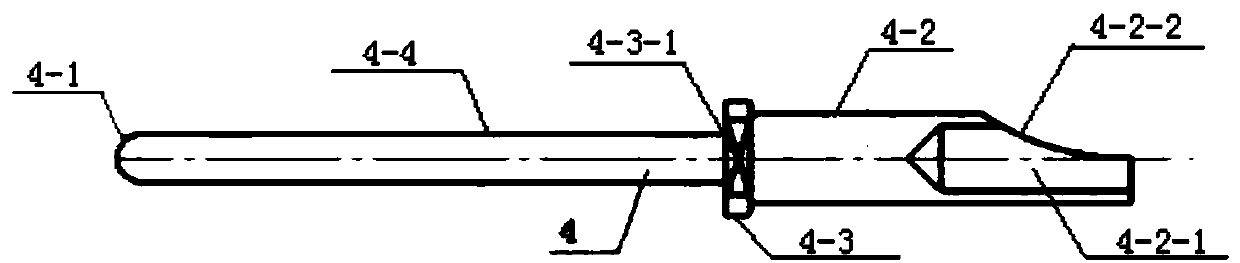
[0051] refer to Figure 4-7, a cutting knife for reversing processing of electrical connector pins, the cutting knife includes a handle 1-1 and a blade 1-2, the handle 1-1 and the blade 1-2 are integrally formed, and the front end of the handle 1-1 is provided with Insert 1-2, insert 1-2 includes rake face 1-2-1, auxiliary flank face 1-2-2, main cutting edge 1-2-3, auxiliary cutting edge 1-2-4 and main relief tool face 1-2-5, the intersection line of the rake face 1-2-1 and the main flank face 1-2-5 forms a linear main cutting edge 1-2-3, and the rake face 1-2- 1 and the minor flank 1-2-2 form a linear minor cutting edge 1-2-4; the main cutting edge 1-2-3 has a main deflection angle α of 55°.

[0052] The handle 1-1 is in the shape of a cuboid.

[0053] The width W of the blade 1-2 1 is 0.7mm.

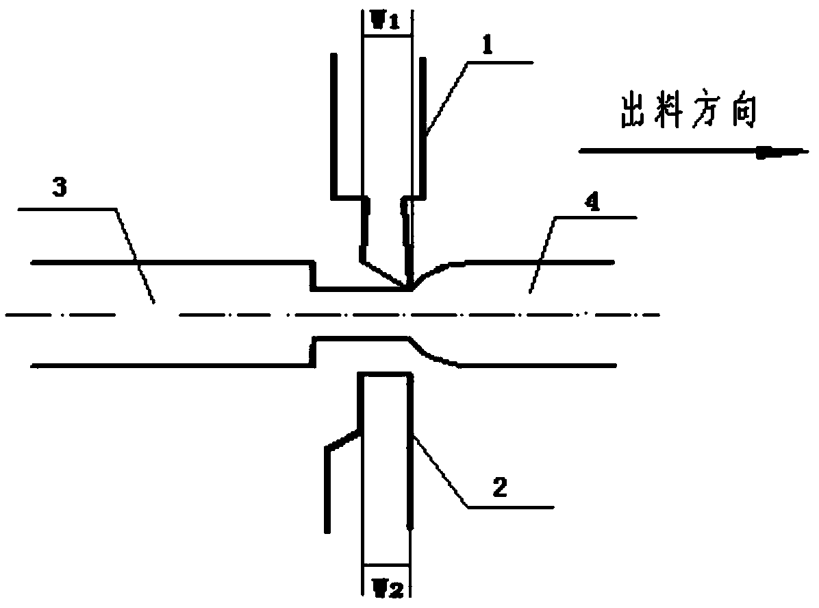
[0054] refer to figure 2 and Figure 9 , using the cutting knife to reverse the method of machining electrical connector pins, the method includes the following steps:

[0055]...

Embodiment 2

[0063] refer to Figure 4-7 , a cutting knife for reversing processing of electrical connector pins, the cutting knife includes a handle 1-1 and a blade 1-2, the handle 1-1 and the blade 1-2 are integrally formed, and the front end of the handle 1-1 is provided with Insert 1-2, insert 1-2 includes rake face 1-2-1, auxiliary flank face 1-2-2, main cutting edge 1-2-3, auxiliary cutting edge 1-2-4 and main relief tool face 1-2-5, the intersection line of the rake face 1-2-1 and the main flank face 1-2-5 forms a linear main cutting edge 1-2-3, and the rake face 1-2- 1 and the minor flank 1-2-2 form a linear minor cutting edge 1-2-4; the main cutting edge 1-2-3 has a main deflection angle α of 60°.

[0064] The handle 1-1 is in the shape of a cuboid.

[0065] The width W of the blade 1-2 1 1.5mm.

[0066] refer to figure 2 and Figure 9 , using the cutting knife to reverse the method of machining electrical connector pins, the method includes the following steps:

[0067] (...

Embodiment 3

[0075] refer to Figure 4-7 , a cutting knife for reversing processing of electrical connector pins, the cutting knife includes a handle 1-1 and a blade 1-2, the handle 1-1 and the blade 1-2 are integrally formed, and the front end of the handle 1-1 is provided with Insert 1-2, insert 1-2 includes rake face 1-2-1, auxiliary flank face 1-2-2, main cutting edge 1-2-3, auxiliary cutting edge 1-2-4 and main relief tool face 1-2-5, the intersection line of the rake face 1-2-1 and the main flank face 1-2-5 forms a linear main cutting edge 1-2-3, and the rake face 1-2- 1 and the minor flank 1-2-2 form a linear minor cutting edge 1-2-4; the main cutting edge 1-2-3 has a main deflection angle α of 50°.

[0076] The handle 1-1 is in the shape of a cuboid.

[0077] The width W of the blade 1-2 1 0.8mm.

[0078] refer to figure 2 and 9 , using the cutting knife to reverse the method of machining electrical connector pins, the method includes the following steps:

[0079] (1) Cente...


PUM

PropertyMeasurementUnit
widthaaaaaaaaaa

Abstract

The invention discloses a cut-off tool for back turning machining of a contact pin of an electric connector and a back turning machining method. The technical problem that in the prior art, a torn portion is generated on a ball R portion in the back turning machining process of a contact pin is solved. The cut-off tool comprises a cutter handle and a blade. The blade is arranged at the front end of the cutter handle, and comprises a front blade face, an auxiliary rear blade face, a main cutting edge, an auxiliary cutting edge and a main rear blade face, wherein the main cutting edge angle alpha of the main cutting edge is 55+ / -5 degrees. The method of conducting back turning machining on the contact pin of the electric connector by use of the cut-off tool comprises the following steps of (1) centring; (2) drilling; (3) R milling; (4) excircle turning; (5) flattening milling; and (6) ball R turning. The steps are accomplished by a set of numerical control longitudinal cutting automaticlathe equipment. By the adoption of the cut-off tool for back turning machining of the contact pin of the electric connector and the back turning machining method, the contact pin is full in ball R portion and is free of the torn portion, the number of the working procedures is reduced, equipment replacement is not required, one-time machining forming is achieved, the percent of pass of products is improved, the cost is reduced, and the production efficiency is improved.

Description

technical field [0001] The invention relates to the field of processing electrical connector contact pieces, in particular to a cutting knife and a pin reverse processing method for electrical connector pin reverse processing. Background technique [0002] As electrical connectors are used more and more widely, there are higher and higher requirements for parts processing accuracy and processing efficiency. The pin is a key component of the electrical connector, which directly affects the reliability of the electrical connector. Most of the contact pins are made of elastic copper alloy material with good electrical conductivity, and the surface is silver-plated and gold-plated to achieve the purpose of small contact resistance and anti-corrosion. [0003] The existing pin production generally adopts the front turning processing method, refer to Figure 8 , the processing steps are the blank under the automatic machine (turning the ball R → turning the outer diameter → turni...

Claims


Application Information

Patent Timeline
Patent Type & Authority Patents(China)
IPC IPC(8): B23B27/00B23P15/00
CPCB23B27/00B23P15/00
Inventor 黄玉石倪博孙禹白群
Owner 沈阳兴华航空电器有限责任公司
Why Eureka
Try Eureka