
Cooling device for cement processing

A cooling device and cement technology, applied in the field of cooling devices, can solve the problems of cement heat dissipation difficulties, high concrete pouring temperature, high cement temperature, etc.

Inactive Publication Date: 2018-06-22
盐城市新驰工贸有限公司
View PDF0 Cites 0 Cited by
  • Summary
  • Abstract
  • Description
  • Claims
  • Application Information

AI Technical Summary

Problems solved by technology

[0003] The purpose of the present invention is to solve the problem that the temperature of bulk cement in the prior art is generally too high when it leaves the factory, and it is difficult to dissipate heat after the cement is transported to the mixing station and put into the warehouse, causing the temperature of the cement to remain high, causing the concrete pouring temperature to be too high, and causing the concrete to suffer from temperature stress. While there are frequent problems with early cracking phenomenon, the proposed cooling device for cement processing

Method used

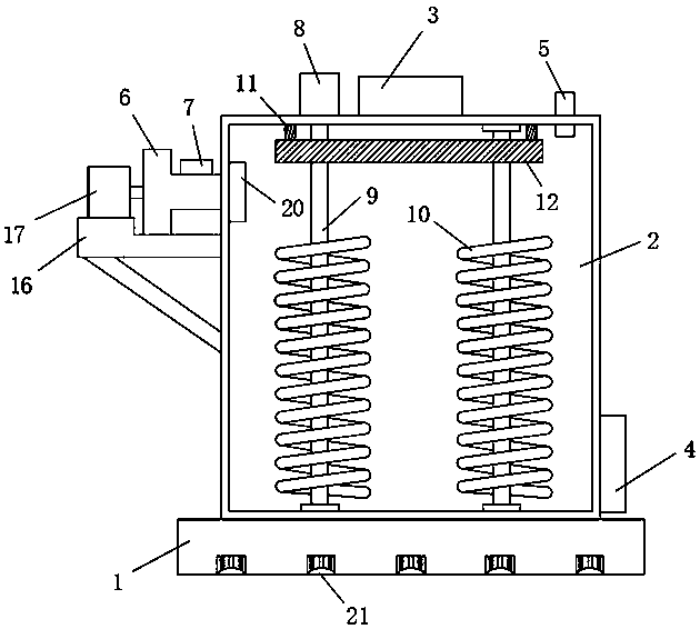
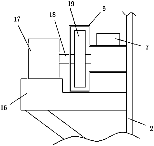
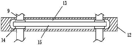

Image

  • Cooling device for cement processing
  • Cooling device for cement processing
  • Cooling device for cement processing

Examples


Embodiment Construction

[0015] The technical solutions in the embodiments of the present invention will be clearly and completely described below in conjunction with the accompanying drawings in the embodiments of the present invention. Obviously, the described embodiments are only a part of the embodiments of the present invention, rather than all the embodiments.

[0016] In the description of the present invention, it should be understood that the terms "upper", "lower", "front", "rear", "left", "right", "top", "bottom", "inner", " The orientation or positional relationship indicated by “outside” is based on the orientation or positional relationship shown in the drawings, and is only for the convenience of describing the present invention and simplifying the description, and does not indicate or imply that the device or element referred to must have a specific orientation to The specific azimuth structure and operation cannot be understood as a limitation of the present invention.

[0017] Reference ...


PUM


Abstract

The invention discloses a cooling device for cement processing. The cooling device comprises a base, a box body is fixedly connected to the upper surface of the base, and a feed inlet and a discharging opening are formed in the box body; the box body is communicated with an air outlet pipe and an air inlet pipe, a valve is arranged on the air inlet pipe, and the valve is located outside the box body; a plurality of air-permeable cloths are arranged at the lower end of the air outlet pipe, and a first motor is arranged on the upper surface of the box body; a first rotating shaft is hinged to the output end of the first motor, and the lower end of the first rotating shaft penetrates through the outer side wall of the box body and is rotationally connected to the inner wall of the box body; arotating shaft is further rotationally connected to the interior of the box body, a transmission structure is arranged between the first rotating shaft and the rotating shaft, and spiral stirring blades are arranged on the first rotating shaft and the rotating shaft. The cooling device is easy to operate and convenient to use, and cement is sufficiently cooled before bulk cement is delivered, sothat unnecessary influences caused by later use are avoided.

Description

Technical field [0001] The present invention relates to the technical field of cooling devices, in particular to a cooling device used for cement processing. Background technique [0002] Compared with bagged cement, bulk cement has the advantages of saving resources, saving packaging costs, reducing costs, and improving labor productivity. The sales price can be reduced by more than 20 yuan per ton compared with bagged cement. At present, cement is shipped in bulk. It has gradually become common in our country. However, in recent years, the temperature of bulk cement leaving the factory is generally too high. After the cement is transported to the mixing station, it is difficult to dissipate heat. This causes the cement temperature to remain high and the concrete pouring temperature is too high. Early cracking occurs frequently due to stress. Summary of the invention [0003] The purpose of the present invention is to solve the problem that the temperature of bulk cement leaving...

Claims


Application Information

Patent Timeline
Patent Type & Authority Applications(China)
IPC IPC(8): C04B7/47
CPCC04B7/47
Inventor 李家梁
Owner 盐城市新驰工贸有限公司
Learn More