
car led lights

A technology for LED lights and vehicles, which is applied to motor vehicles, road vehicles, and vehicle parts, etc. It can solve problems such as maintenance personnel's troubles, device temperature rise, and LED lights burnout, and achieve the effect of facilitating long-term work

Active Publication Date: 2020-06-30
广州科瑞创新科技有限公司
View PDF6 Cites 0 Cited by
  • Summary
  • Abstract
  • Description
  • Claims
  • Application Information

AI Technical Summary

Problems solved by technology

[0002] LED lamp is a solid-state semiconductor device that can convert electrical energy into visible light. Due to its good shock resistance, LED lamps are widely used in the production of daily electrical appliances and machinery such as mobile phones, table lamps, and home appliances. At present, when installing LED lamps, Usually, the lamp bead is directly welded to the light strip, and then the light strip is welded to the light board. Since multiple lamp beads are welded on the light strip, when one lamp bead is damaged, the entire Remove the lamp strip and wire, and then take out the damaged lamp bead. Although the welded lamp bead is firm, it will cause a lot of trouble to the maintenance personnel when it is disassembled and repaired. In addition, when multiple lamp beads work together, The heat generated will cause the temperature of the whole device to rise rapidly. If the temperature is not cooled, it may cause the LED lamp to burn out. Therefore, a new type of automotive LED lamp is needed to solve the above problems

Method used


Image

  • car led lights
  • car led lights
  • car led lights

Examples


Embodiment Construction

[0021] The following will clearly and completely describe the technical solutions in the embodiments of the present invention with reference to the accompanying drawings in the embodiments of the present invention. Obviously, the described embodiments are only some, not all, embodiments of the present invention. Based on the embodiments of the present invention, all other embodiments obtained by persons of ordinary skill in the art without making creative efforts belong to the protection scope of the present invention.

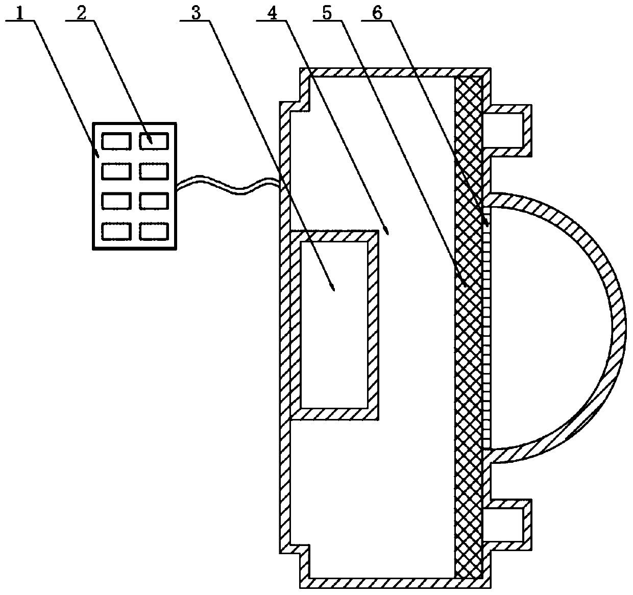
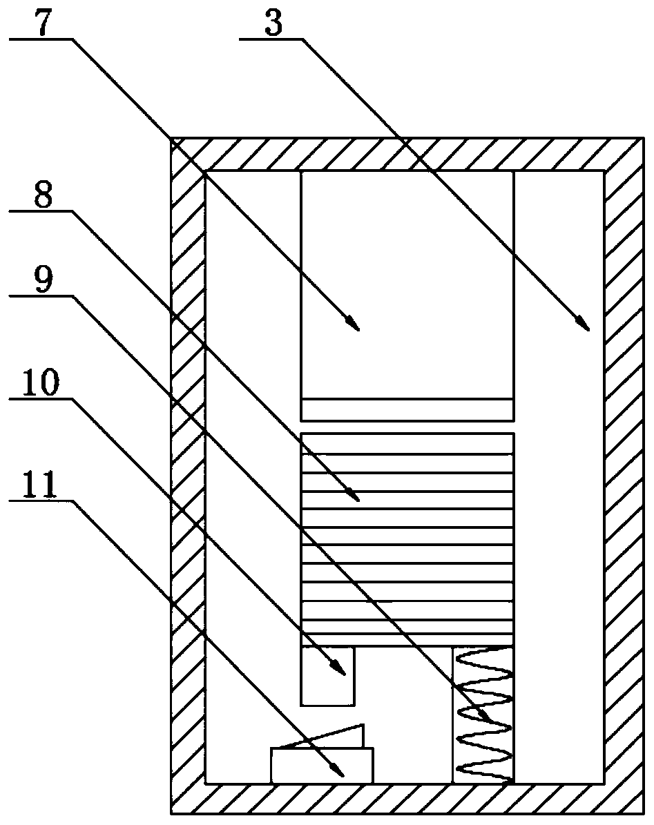
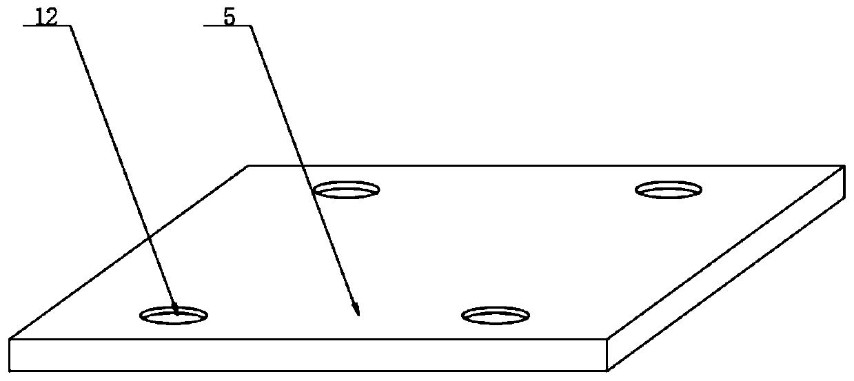
[0022] see Figure 1-7 , the present invention provides a technical solution: LED lights for vehicles, including a control panel 1, a control button 2, a radiator 3, a protective shell 4, a fixing plate 5, a lamp plate 6, a permanent magnet 7, a temperature sensing magnet 8, a first Spring 9, striker 10, reset switch 11, connection port 12, connection column 13, groove 14, fixed port 15, fixed rod 16, electric push rod 17, second spring 18, metal sheet 19, LED...


PUM


Abstract

The invention discloses a vehicle LED lamp comprising a control panel, control buttons, a radiator, a protection shell, a fixing plate, a lamp panel, a permanent magnet, a temperature sensing magnet,a first spring, a firing pin, a reset switch, a connecting port, a connecting column, a groove, a fixing opening, a fixing rod, an electric push rod, a second spring, a metal sheet, an LED lamp body,a sponge mat, a pressing piece, a threaded rod, a reflecting cover and a threaded hole. The protection shell is connected with the control panel through a wire, and the control buttons are arranged onone side of the control panel. The radiator is arranged inside the protection shell, and the permanent magnet is arranged in the radiator. The temperature sensing magnet is arranged on one side of the permanent magnet, and the firing pin is arranged at the bottom of the temperature sensing magnet. The reset switch is mounted on one side of the firing pin, the first spring is mounted on one side of the reset switch, and the fixing plate is arranged on one side of the radiator. The vehicle LED lamp is easy and convenient to mount and has a good heat dissipation function.

Description

technical field [0001] The invention relates to the technical field of LED lamp equipment, in particular to an LED lamp for vehicles. Background technique [0002] LED lamp is a solid-state semiconductor device that can convert electrical energy into visible light. Due to its good shock resistance, LED lamps are widely used in the production of daily electrical appliances and machinery such as mobile phones, table lamps, and home appliances. At present, when installing LED lamps, Usually, the lamp bead is directly welded to the light bar line, and then the light bar line is welded to the light board. Since multiple lamp beads are welded on the light bar line, when one lamp bead is damaged, the entire Remove the lamp strips and wires, and then take out the damaged lamp beads. Although the welded lamp beads are firm, they will cause a lot of trouble to the maintenance personnel when they are disassembled and repaired. In addition, when multiple lamp beads work together, The h...

Claims


Application Information

Patent Timeline
Patent Type & Authority Patents(China)
IPC IPC(8): F21S45/00F21S45/40F21S45/49F21V17/10F21V17/12F21V17/16F21V19/00F21W107/10F21Y115/10
CPCF21V17/101F21V17/12F21V17/162F21V19/0025F21Y2115/10
Inventor 眭世荣侯晋华陈可琪黄映仪
Owner 广州科瑞创新科技有限公司
Learn More