High-speed feeding device of compounding machine

A technology of feeding device and composite machine, applied in the direction of feed, food science, application, etc., to achieve the effect of prolonging the service life, increasing the burden of the motor, and reducing waste

Inactive Publication Date: 2017-11-28
海盐派特普科技有限公司
View PDF3 Cites 0 Cited by
  • Summary
  • Abstract
  • Description
  • Claims
  • Application Information

AI Technical Summary

Problems solved by technology

When the invention is stirring, the stirred material will not be bonded to the stirring rod, will not increase the working load of the motor, reduce the loss of electric energy, and does not need to clean the stirring rod, saving labor, but the stirring material of the device Quality needs further improvement

Method used


Image

  • High-speed feeding device of compounding machine
  • High-speed feeding device of compounding machine

Examples


Embodiment 1

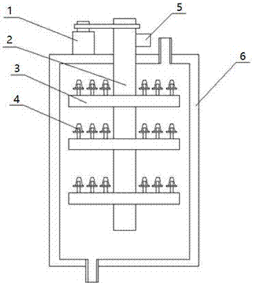
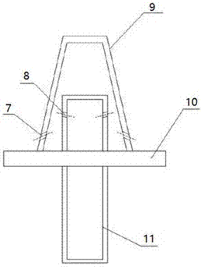
[0014] like Figure 1-2 As shown, a high-speed feeding device of a compound machine includes a stirring tank 6, a stirring shaft 2 arranged inside the stirring tank 6, a material inlet is provided on the side of the top of the stirring tank 6, and a material outlet is provided on the side of the bottom of the mixing tank 6, Stirring shaft 2 is placed outside the axis of stirring tank 6, and the top of stirring shaft 2 is placed outside stirring tank 6. Stirring shaft 2 outside stirring tank 6 is connected with motor 1 and air pump 5. Stirring rods 3 are evenly distributed on the surface of stirring shaft 2. Stirring The air blowing pipe 4 is evenly distributed on the rod 3, the stirring shaft 2 and the stirring rod 3 are hollow structures, the upper end of the stirring rod 3 is provided with evenly distributed air outlets, the air outlets are connected with the air blowing pipe 4 correspondingly, and the distance between the air outlets is 3 1 / 4 of the total length, the air bl...

Embodiment 2

[0016] like figure 1 , 2 As shown, when the high-speed feeding device of a compound machine of the present invention is actually used: a material outlet is provided on the side of the bottom of the closed mixing tank 6, and the material is poured from the material inlet provided on the side of the top of the mixing tank 6, and the motor 1 Drive the stirring shaft 2 to rotate and drive the stirring rod 3 to stir the materials. At the same time, the air pump 5 starts, and the gas is blown out from the blowing pipe 4 to prevent the material from adhering to the surface of the stirring rod 3. The surface of the stirring rod 3 and the stirring shaft 2 is coated with anti-rust The coating can effectively avoid the impact of corrosion on the quality of the material, and the anti-rust coating also has the function of preventing the material from adhering to the surface of the stirring rod 3 and the stirring shaft 2. When the stirring is completed, open the bottom side of the mixing ta...


PUM


Abstract

The invention discloses a high-speed feeding device of a compounding machine. The high-speed feeding device comprises a stirring tank and a stirring shaft arranged in the stirring tank; one side of the top of the stirring tank is provided with a material inlet; one side of the bottom of the stirring tank is provided with a material outlet; the stirring shaft is arranged at an axis of the stirring tank; the top of the stirring shaft is arranged outside the stirring tank; the portion, outside the stirring tank, of the stirring shaft is connected with a motor and an air pump; the surface of the stirring shaft is uniformly distributed with stirring rods; and the stirring rods are uniformly distributed with air blowpipes. Materials stirred by the feeding device are not easy to adhere to stirring arms, and a stirring mechanism is not required to clean. The surface of the stirring mechanism is coated with an antirust coating, and the materials are not influenced by corrosion, thereby prolonging service lifetime of the stirring mechanism and facilitating maintenance.

Description

technical field [0001] The invention belongs to the field of feed processing devices, in particular to a high-speed feeding device for a composite machine. Background technique [0002] Feed mixing is a necessary step for farms. The way of feeding and mixing is manual mixing, which is time-consuming and labor-intensive. Feed mixers are gradually being used now. However, at present, most feed mixers use a set of electric motors to drive the stirring shaft and stirring blades to stir the feed. This single mixing method takes a long time and has low mixing efficiency, which inevitably leads to the problem of stratification in the mixing of feed. That is, there is a phenomenon that the feed is not evenly stirred. [0003] Prior art, such as the patent document of Chinese invention authorization, the authorized announcement number CN 104689748 A, this invention discloses a kind of agitator for feed production, including a shell, a feeding device and a motor, the motor is install...

Claims


Application Information

Patent Timeline
Patent Type & Authority Applications(China)
IPC IPC(8): A23N17/00
CPCA23N17/007
Inventor 王妍
Owner 海盐派特普科技有限公司
Why Eureka
Try Eureka