Soil sampling device for laying of hydraulic engineering pipelines

A technology for soil sampling and water conservancy engineering, which is applied in sampling devices and other directions, and can solve the problems of complex operation, unstable sampling, and low sampling efficiency.

Inactive Publication Date: 2018-06-22
汪雄辉
View PDF9 Cites 4 Cited by
  • Summary
  • Abstract
  • Description
  • Claims
  • Application Information

AI Technical Summary

Problems solved by technology

[0005] In order to overcome the shortcomings of the existing soil sampling equipment for laying water conservancy engineering pipelines, such as low sampling efficiency, insufficient stability during sampling, and complicated operation, the technical problem to be solved by the present invention is to provide a soil sampling device with high sampling efficiency, sufficient stability during sampling, and easy operation. Simple Soil Sampling Equipment for Pipeline Laying in Water Conservancy Projects

Method used


Image

  • Soil sampling device for laying of hydraulic engineering pipelines
  • Soil sampling device for laying of hydraulic engineering pipelines
  • Soil sampling device for laying of hydraulic engineering pipelines

Examples


Embodiment 1

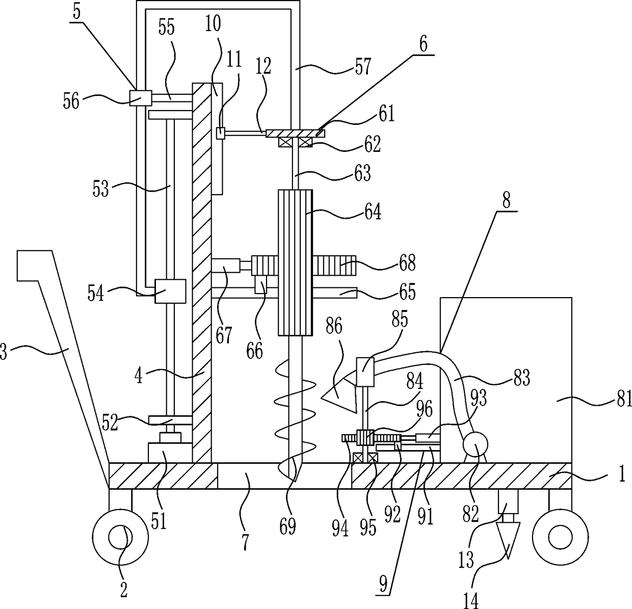
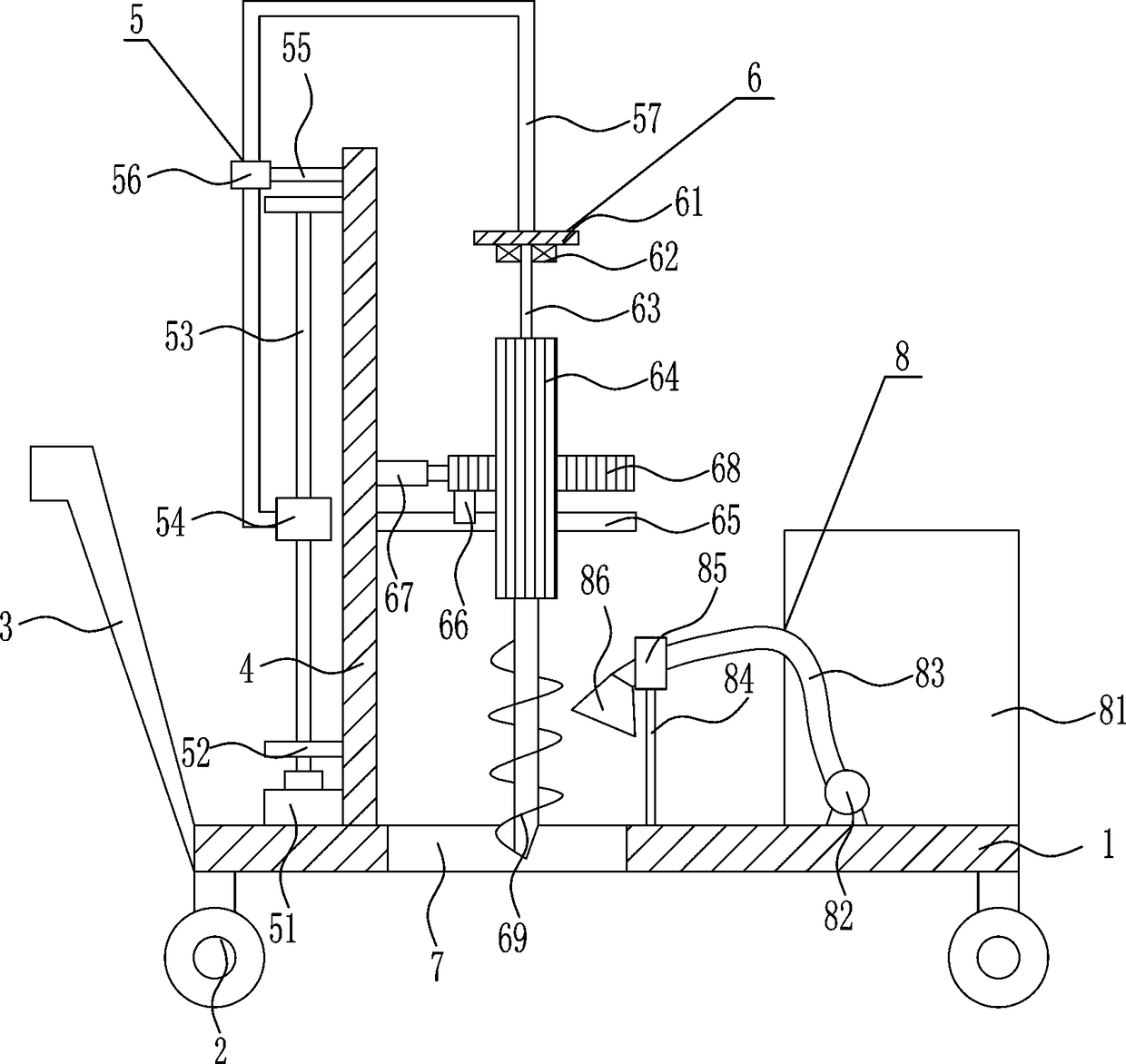
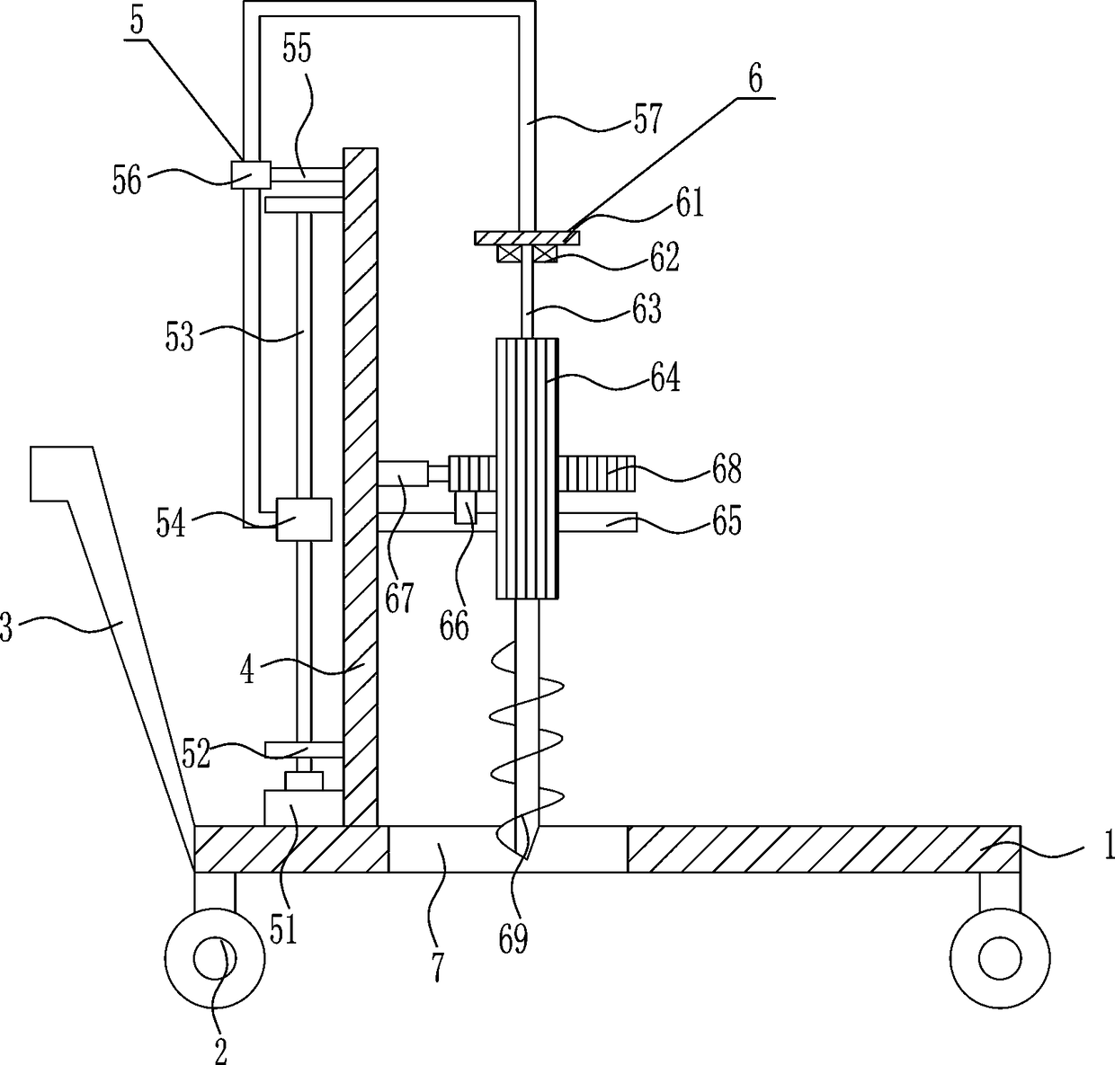
[0030] A kind of soil sampling equipment for pipeline laying of water conservancy projects, such as Figure 1-4As shown, it includes base plate 1, wheel 2, push handle 3, vertical plate 4, driving mechanism 5 and drilling mechanism 6, the bottom of base plate 1 is provided with wheel 2, the left end of base plate 1 is provided with push handle 3, and the left side of base plate 1 is provided with Riser 4, bottom plate 1 left part has through hole 7, and the left side of riser 4 is provided with driving mechanism 5, and riser 4 right side is provided with drilling mechanism 6.

Embodiment 2

[0032] A kind of soil sampling equipment for pipeline laying of water conservancy projects, such as Figure 1-4 As shown, it includes base plate 1, wheel 2, push handle 3, vertical plate 4, driving mechanism 5 and drilling mechanism 6, the bottom of base plate 1 is provided with wheel 2, the left end of base plate 1 is provided with push handle 3, and the left side of base plate 1 is provided with Riser 4, bottom plate 1 left part has through hole 7, and the left side of riser 4 is provided with driving mechanism 5, and riser 4 right side is provided with drilling mechanism 6.

[0033] The driving mechanism 5 includes a motor 51, a first bearing seat 52, a screw rod 53, a nut 54, a cross bar 55, a guide sleeve 56 and a guide rod 57. The left side of the bottom plate 1 is provided with a motor 51, and the left side of the vertical plate 4 is symmetrical up and down. A first bearing seat 52 is provided, and a screw mandrel 53 is arranged between the two first bearing seats 52. T...

Embodiment 3

[0035] A kind of soil sampling equipment for pipeline laying of water conservancy projects, such as Figure 1-4 As shown, it includes base plate 1, wheel 2, push handle 3, vertical plate 4, driving mechanism 5 and drilling mechanism 6, the bottom of base plate 1 is provided with wheel 2, the left end of base plate 1 is provided with push handle 3, and the left side of base plate 1 is provided with Riser 4, bottom plate 1 left part has through hole 7, and the left side of riser 4 is provided with driving mechanism 5, and riser 4 right side is provided with drilling mechanism 6.

[0036] The driving mechanism 5 includes a motor 51, a first bearing seat 52, a screw rod 53, a nut 54, a cross bar 55, a guide sleeve 56 and a guide rod 57. The left side of the bottom plate 1 is provided with a motor 51, and the left side of the vertical plate 4 is symmetrical up and down. A first bearing seat 52 is provided, and a screw mandrel 53 is arranged between the two first bearing seats 52. T...


PUM


Abstract

The invention relates to soil sampling equipment, especially to a soil sampling device for laying of hydraulic engineering pipelines. The objective of the invention is to provide the soil sampling device with high sampling efficiency, sufficient stability in sampling and simple operation. The soil sampling device for laying of hydraulic engineering pipelines comprises a base plate and the like, wherein the bottom of the base plate is provided with wheels; a pushing handle is arranged on the left end of the base plate; a vertical plate is arranged on the left side of the top of the base plate;a through hole is formed in the left part of the base plate; a driving mechanism is arranged on the left side of the vertical plate; and a drilling mechanism is arranged on the right side of the vertical plate. The soil sampling device provided by the invention achieves the effects of high sampling efficiency, sufficient stability during sampling and simple operation; the operation of the drivingmechanism drives the water tank of the drilling mechanism to move, and the operation of the drilling mechanism is controlled at the same time, so downward drilling of the ground can be realized, and drilling efficiency is high; and a rotary mechanism makes watering more uniform, and so drilling efficiency is further improved.

Description

technical field [0001] The invention relates to a soil sampling device, in particular to a soil sampling device for laying water conservancy engineering pipelines. Background technique [0002] Water conservancy projects are projects built to control and allocate natural surface water and groundwater to achieve the purpose of eliminating harm and rejuvenating profits. Also known as water engineering. Water is an indispensable precious resource for human production and life, but its natural state does not fully meet human needs. Only by building water conservancy projects can we control water flow, prevent floods, and regulate and distribute water to meet the needs of people's life and production for water resources. Water conservancy projects need to build different types of hydraulic structures such as dams, dikes, spillways, sluices, water inlets, channels, canals, rafts, and fishways to achieve their goals. [0003] During the construction of water conservancy projects...

Claims


Application Information

Patent Timeline
Patent Type & Authority Applications(China)
IPC IPC(8): G01N1/08
Inventor 钱东涂晨妍蔡亚茜
Owner 汪雄辉
Why Eureka
Try Eureka