Electronic component manufacturing method

A technology of electronic components and manufacturing methods, applied in the direction of electrical components, semiconductor/solid-state device manufacturing, circuits, etc., can solve the problems of resin overflowing to the bottom of the chip, easy impact leads, chip scrapping, etc., to prevent clogging and sealing Good performance, good injection molding effect

Active Publication Date: 2018-06-22
重庆市长寿区普爱网络科技有限公司
View PDF8 Cites 6 Cited by
  • Summary
  • Abstract
  • Description
  • Claims
  • Application Information

AI Technical Summary

Problems solved by technology

[0004] However, there are still the following defects in the current injection molding process: resin is injected from the side of the mold, not only it is easy for the resin to overflow to the bottom of the chip, resulting in overflow; moreover, the resin is easy to impact the lead wire at the end of the chip near the injection port, making each lead wire Under the action of the fluid, there is an offset and contact between them, causing a short circuit of the wires, resulting in the scrapping of the chip; increasing the defective rate of the product

Method used


Image

  • Electronic component manufacturing method

Examples


Embodiment 1

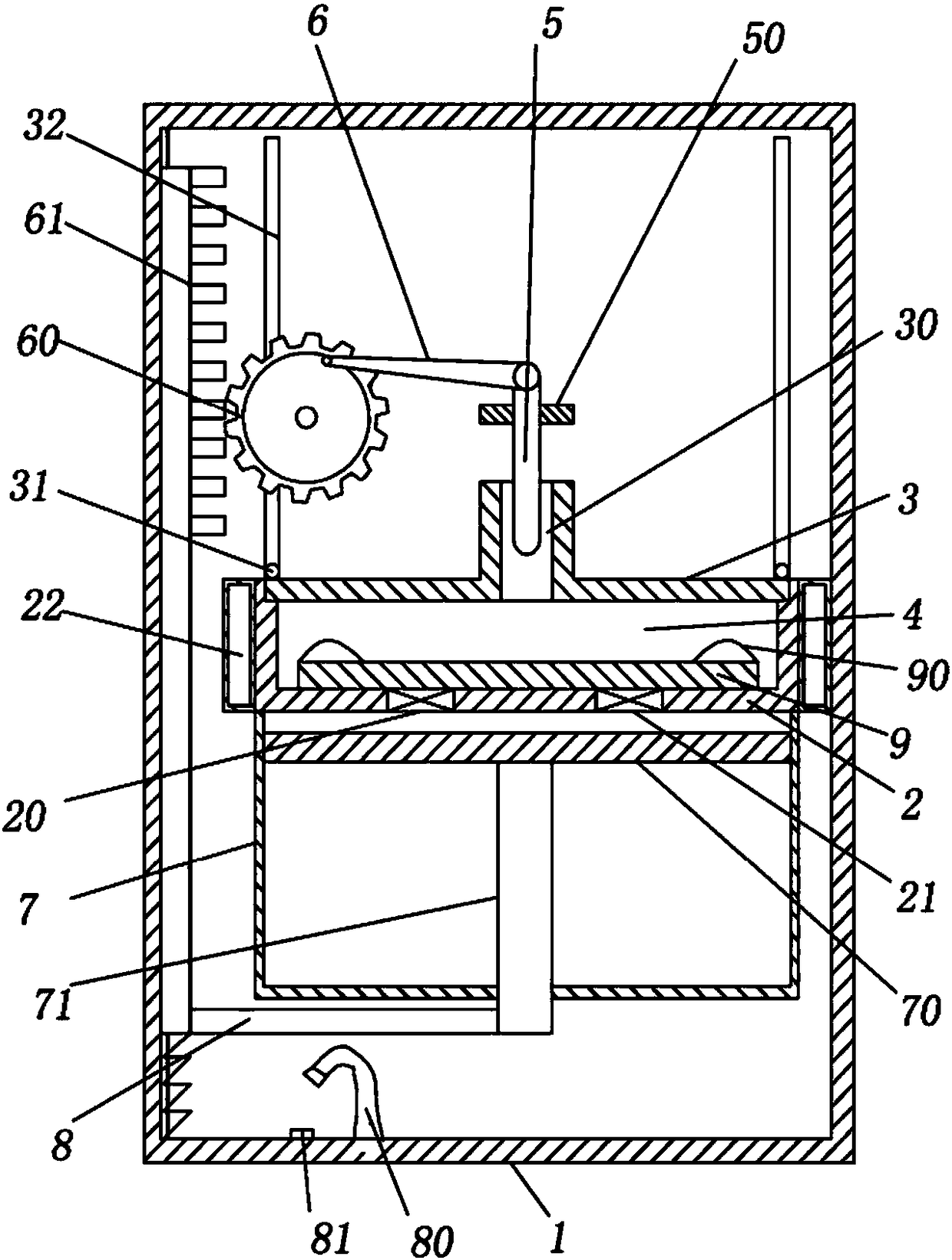
[0027] Basic as attached figure 1 Shown:

[0028] The manufacturing method of the electronic components adopts an injection mold for plastic sealing, and the injection mold includes a frame 1, a mould, a drainage mechanism and an air control mechanism.

[0029] The overall mold is in the shape of a cylinder, including a fixing groove 2 and a cover plate 3 . The top of the fixing groove 2 is open, and an annular groove is provided on the side wall of the top of the fixing groove 2; Port 21; the outer circumference of the fixing groove 2 is provided with an annular cooling groove 22 for cooling the mould. The cover plate 3 is used to cover the top of the fixing groove 2 , and the cover plate 3 is slidably connected in the groove on the top of the fixing groove 2 ; the center of the cover plate 3 is provided with a raised injection port 30 . An injection molding cavity 4 is formed between the fixing groove 2 and the cover plate 3 . In order to give the cover plate 3 enough sl...

Embodiment 2

[0039] The difference between this embodiment and Embodiment 1 is: when the gas is preset in step A, the piston rod is pulled down until the distance between the piston rod and the top of the cylinder is equal to one-eighth of the height of the cylinder; Cool and form.


PUM


Abstract

The invention belongs to the technical field of production of electronic products, and specifically relates to an electronic component manufacturing method. An injection mold is adopted to perform plastic package, and the injection mold includes a rack, a mold, a drainage mechanism and an air control mechanism. The steps of plastic package include A, prearranging gas; B, feeding; C, injection; D,cooling molding; and E, demolding. In Step A, a piston rod is pulled downward, so that gas enters into a cylinder; in Step B, chips are put at the bottom of a fixed groove, the piston rod is continuedto be pulled downward, and the chips are fixed; in Step C, molten plastic package resin is injected into the fixed groove from a drainage rod, and at the same time, the piston rod is continued to bepulled downward; in Step D, the piston rod is fixed, the mold is cooled, and the plastic package resin is molded; and in Step E, the piston rod and sliding racks move upward, and demolding is performed. By adoption of the scheme, rein can be effectively prevented from flowing to the bottoms of the chips in the injection molding process, the risk of a chip lead short circuit is reduced, and the product yield is improved.

Description

technical field [0001] The invention belongs to the technical field of electronic product production, and in particular relates to a method for manufacturing electronic components. Background technique [0002] There are many classifications of electronic components. Individual devices such as resistors and capacitors are called basic devices, while chips integrate many basic devices into a very small circuit board, so they are also called integrated circuits. The chip is small in size and is the most important part of electronic products, undertaking the functions of computing and storage. The complete process of chip production includes several links such as chip design, chip production, packaging production, and cost testing. Among them, chip packaging is to install a shell outside the semiconductor integrated circuit chip, so as to place, fix, seal, protect and enhance the electrothermal performance of the chip, and the packaging process is also a bridge between the int...

Claims


Application Information

Patent Timeline
Patent Type & Authority Applications(China)
IPC IPC(8): H01L21/56
CPCH01L21/56
Inventor 李天翼
Owner 重庆市长寿区普爱网络科技有限公司
Why Eureka
Try Eureka